Upper Door Hinge
I want to replace the upper door hinge (the one circled in red in the picture above) on the butterfly doors.

The primary hinge is a billet aluminum piece in the middle of the door. The top hinge mostly guides the door, so it’s not a structural or safety-related part. The two billet aluminum pieces on top of the roof are simply connected via a small ball joint which provides the rotation and a little twisting (i.e., movement on two planes). It works, but it sticks out like a sore thumb and I want to move it from the exterior to the interior of the car. IMO it could be achieved with a very large trunk-style hinge with a ball joint, but that would project too far into the cockpit. There is a 1.5” OD roll hoop in that location, so there is at least that much room to conceal the mechanics. It will take a little head scratching to figure out the geometry and draw it up in CAD. I use SolidWorks, but if the solution/geometry is figured out in another CAD tool, it shouldn’t be difficult to transfer to a parametric model in SolidWorks. Prototypes will be laser cut or 3D printed and final version will be either laser cut or CNC’d.
The video below shows the door opening, closing and the emergency release being activated.
Note that the piece mounted to the door has rotated on two planes; approximately 75 degrees vertically and 25 degrees transversely. Whatever the actual angles are isn’t critical per say because they are driven by the geometry of the main hinge.

Note the lateral rotation of the piece mounted to the door

Note that the ball joint has rotated in the transverse plane
The stock hinge is mounted to the fiberglass roof via four bolts (i.e., two in each piece). The new hinge will be attached to a plate welded to the 1.5” OD roll cage hoop. The hoop will be covered with a custom A-pillar cover. We could have an equal size blister on the inside of the door to help conceal the hinge when the door is closed. We could go bigger, but if it extends past a tight fitting A-pillar cover it will be noticeable when driving.
Below are some notes for the basic closed geometry. I didn’t get around to modeling the end location. I’ll email you the SolidWorks file.

Main Hinge

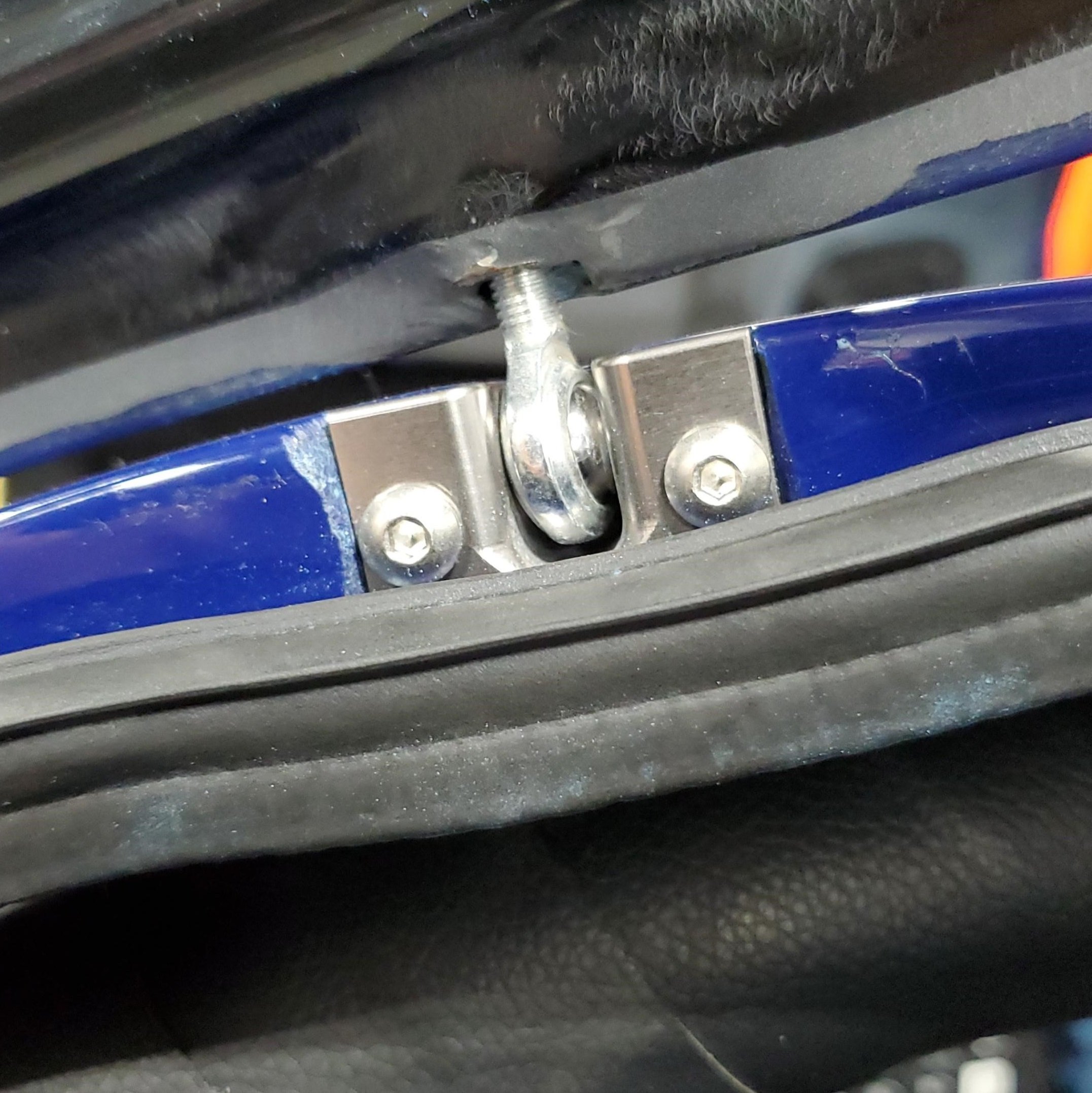
Main hinge pivot point. The photo was taken when the door was fully open. Note the orientation of the rod end. It has less rotation than the upper hinge.

The top billet piece is the main hinge and the lower extruded piece is the actuator arm. The main hinge is bolted solid to the door.
PROTOTYPE CAR APPROACH
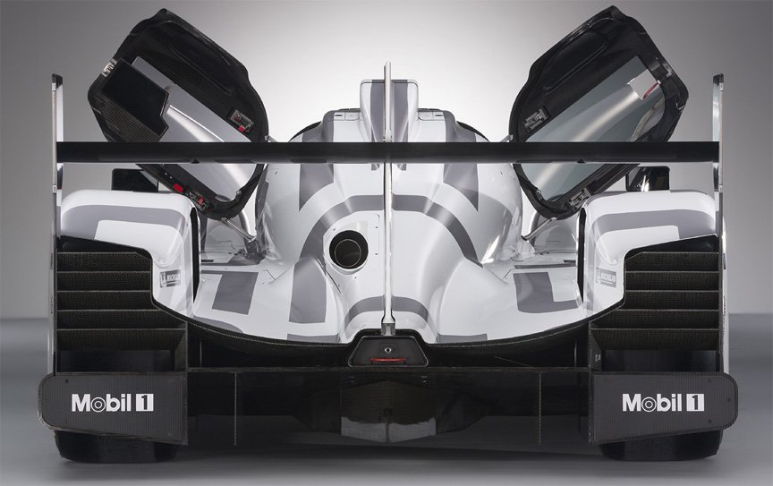
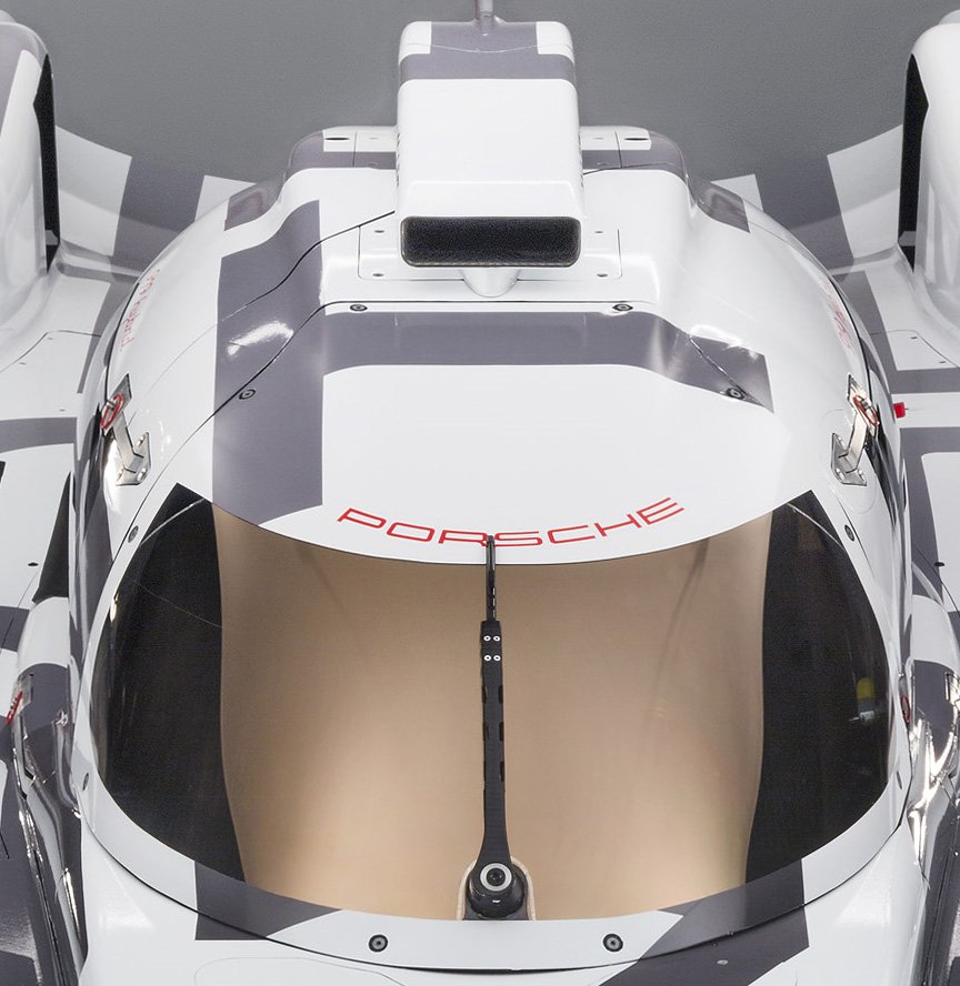
If it proves difficult or impossible to internally conceal the hinge, we could take the approach of the prototype cars shown below. While these allow the driver or someone outside the car to disengage the hinge, that’s a lot of work and not of use to me unless I do the same for the main hinge. The reason that I haven’t tried this yet is because I’d rather have the body clean and wind noise and water ingress are issues with these cars. In addition, there is very little structure in the roof at that point which also interfaces with the windshield.
If I took this approach, I think that I would have nothing externally visible on the door and thin arm flush with the roof line. Here are several prototype cars.


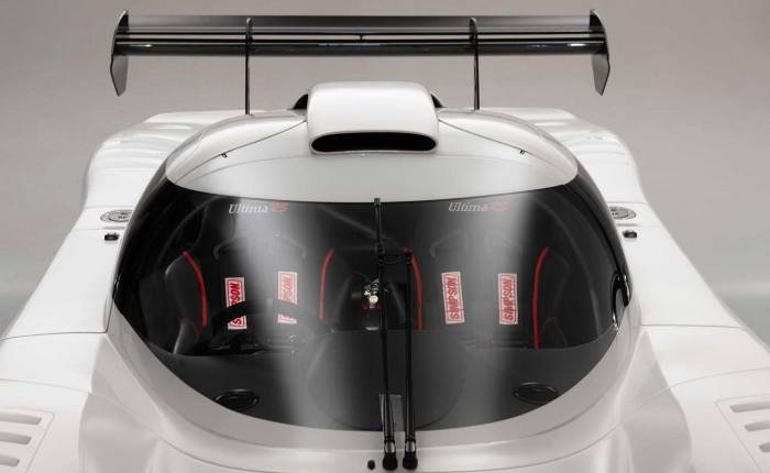
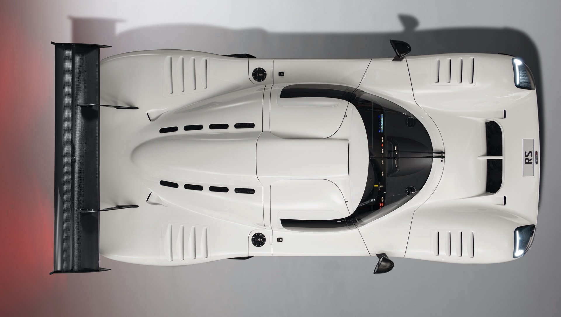
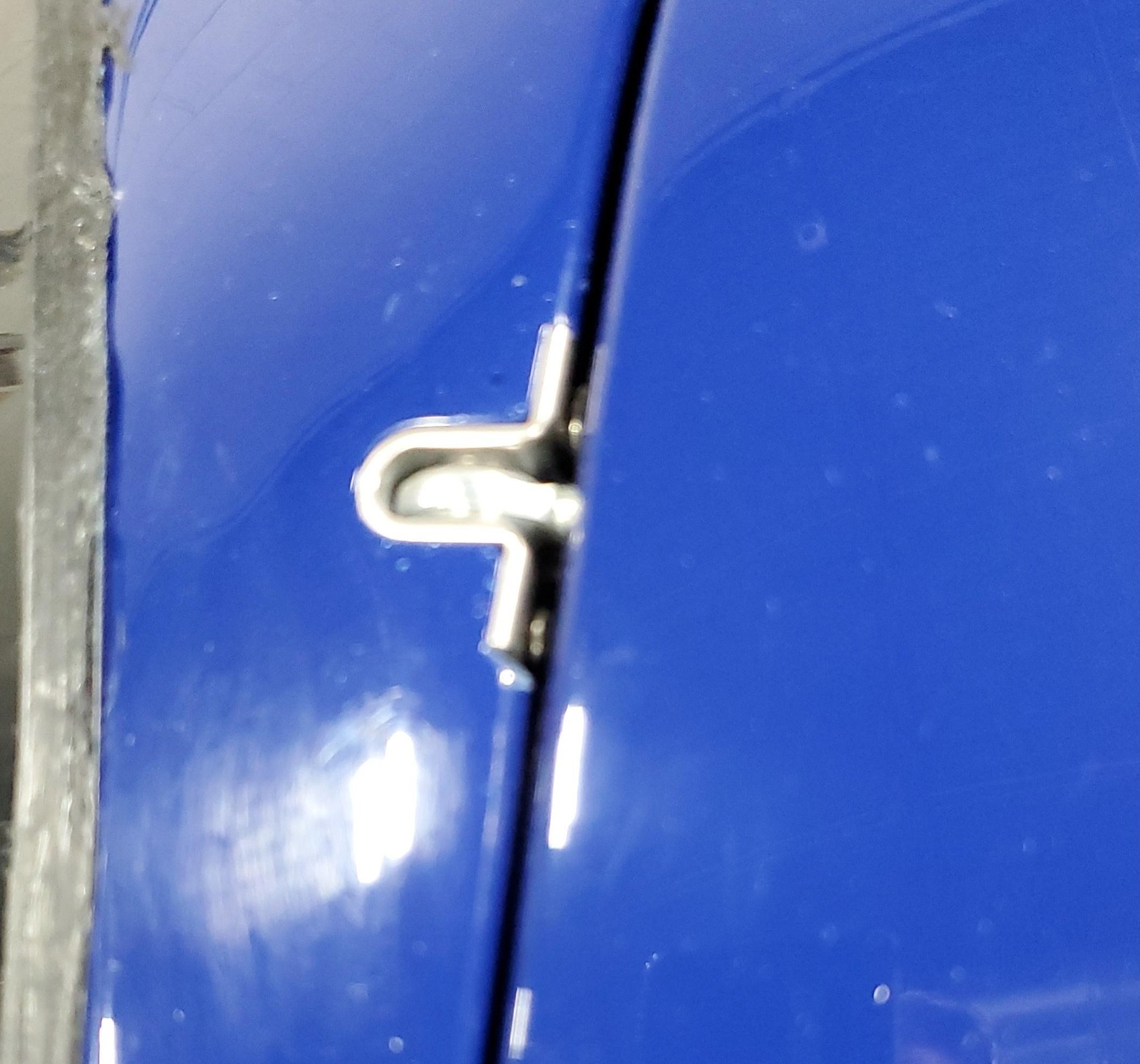
The Ultima RS show below looks pretty good at a distance (white car), but not so great close up (blue car). I would have thought that they would have integrated a small cover for it.