Heat Shields for Exhaust System

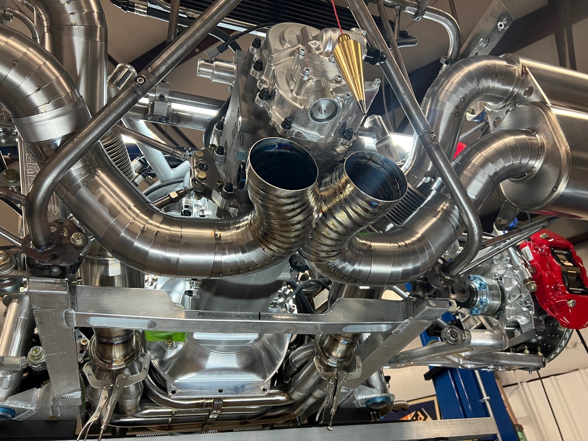
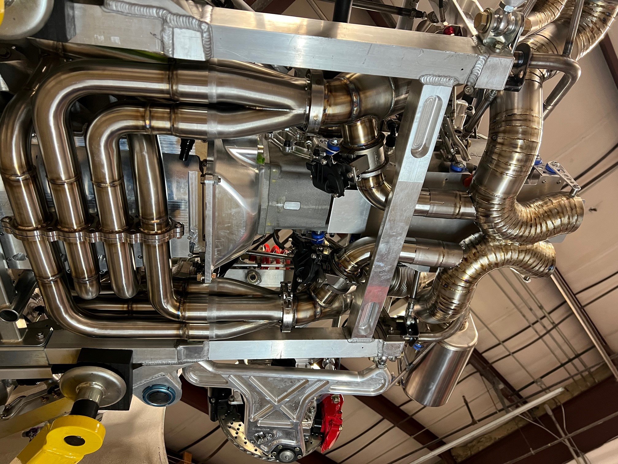
I’ve been building a custom mid-engine monocoque for the last seven years. It’s primarily a street car, but it will see some track days. It’s my version of a halo car, so it’s a blend of form and function. The engine is a fully-built LS7 producing a little over 1,000HP at redline and 800+ lb-ft at 2,000 RPMs on 93 octane. With that type of power in a relatively lightweight car, the objective for the exhaust system was something that sounded different than a lumpy LS. There wasn’t room for an 8:1, so I went with equal-length, 180-degree crossover headers. Due to fitment reasons, the primaries cross under the dry sump pan rather than over the bellhousing like a GT40 bundle of snakes. The cat-back system is 3.5” titanium (the picture above has tacked pie cuts, but the welding has since been finished).
I summary, I have created some issues with heat management issues that I need help with. I live in Boston USA and I think the following approach makes sense:
Some parts could be shipped to the UK to be insulted and shielded
There are a couple of heatshields that can be defined in CAD and can be fabricated in the UK.
There are a couple of areas where I need some consulting on the best approach.
Headers


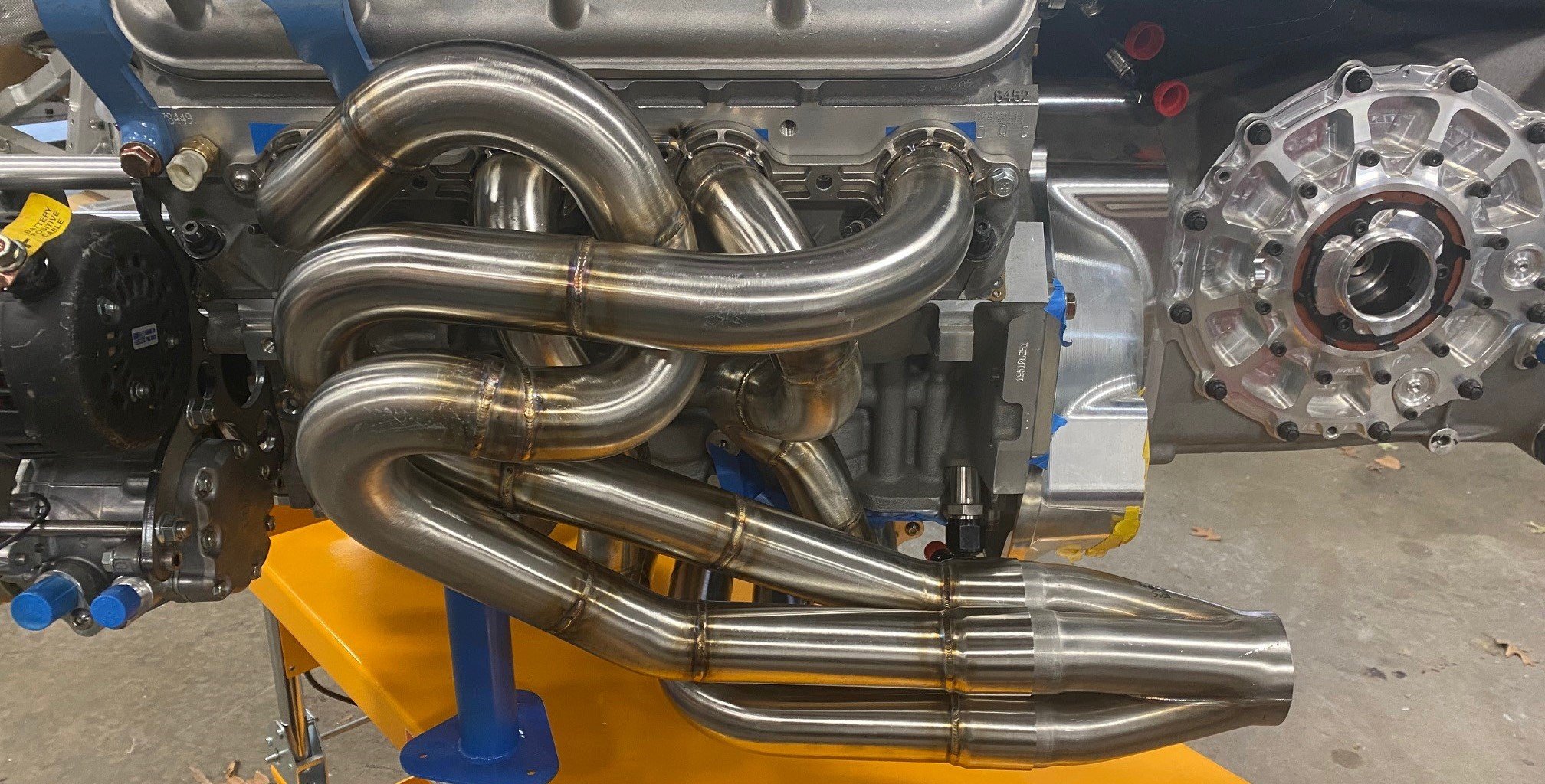
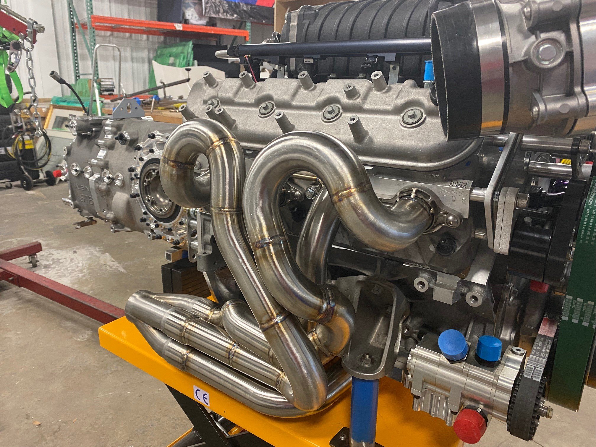
Headers are 321 stainless steel; 1-7/8” stepped to 2”.
They are currently raw, but the plan is to Cerakote (ceramic) coat them.
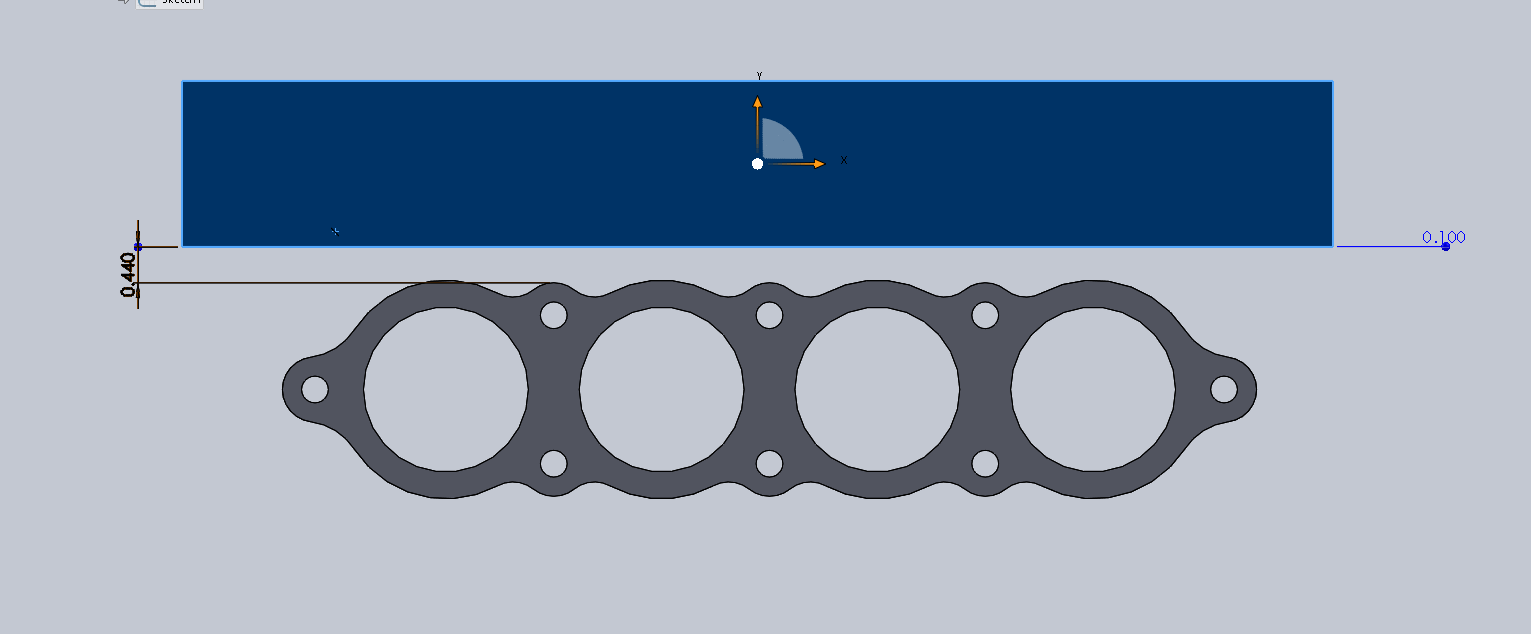
Need a heat shield between the tubes and the bottom of the dry sump pan. I believe that I can replace some of the screws in the pan with longer screws and titanium spacers. The heat shield is primarily flat, but it needs to bend up to protect the side of the pan. There is 0.44” between the top of flange and the bottom of the pan. It may also make sense to bump it up over the flanges.
Potentially insulate the tubes under the oil pan with clam shell insulation. I don’t want to ship the headers and clamshells can be removed.
Catalytic Converter Assemblies
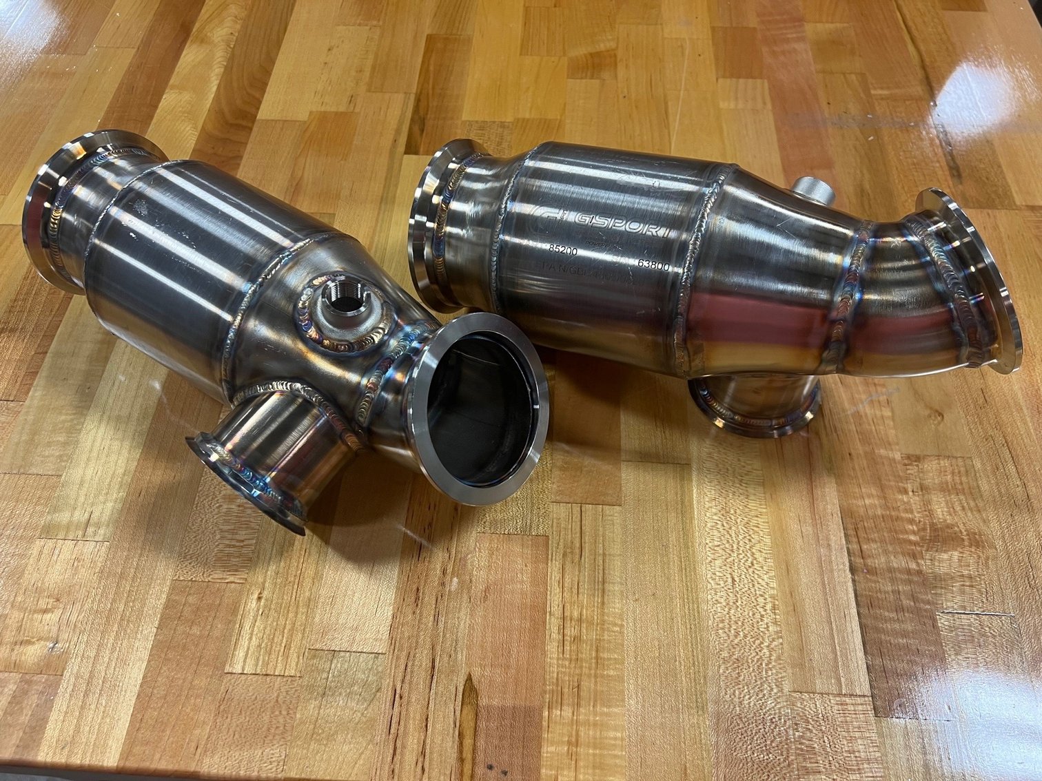
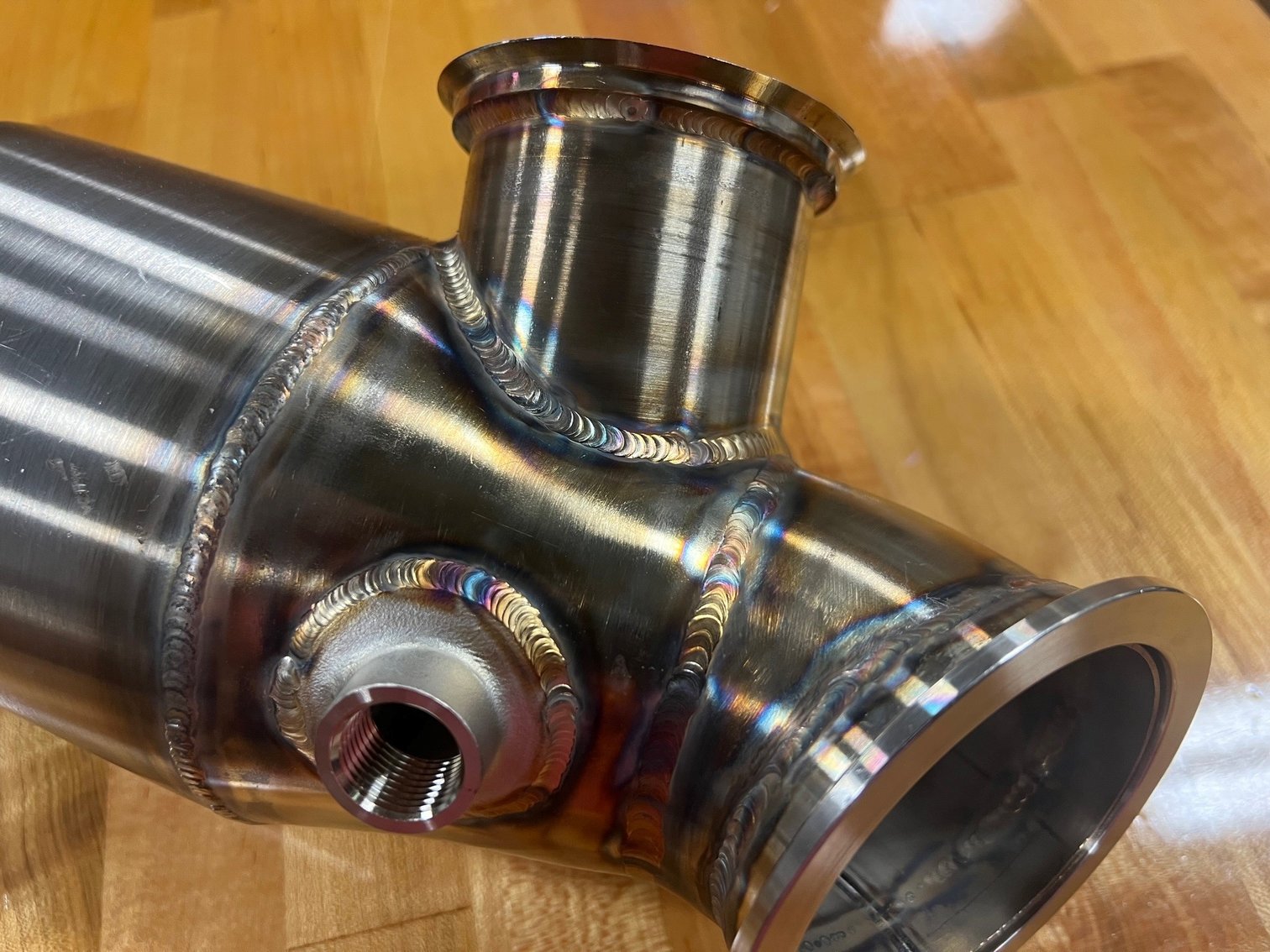
Cerakote (ceramic) coat them.
Apply integral insulation. They’re relatively small and can be easily shipped.
Each catalytic convert has tight clearance in one location (apparent in the third picture). There is 0.25 clearance between the bottom apex of the converter and the corner of a billet aluminum chassis member.
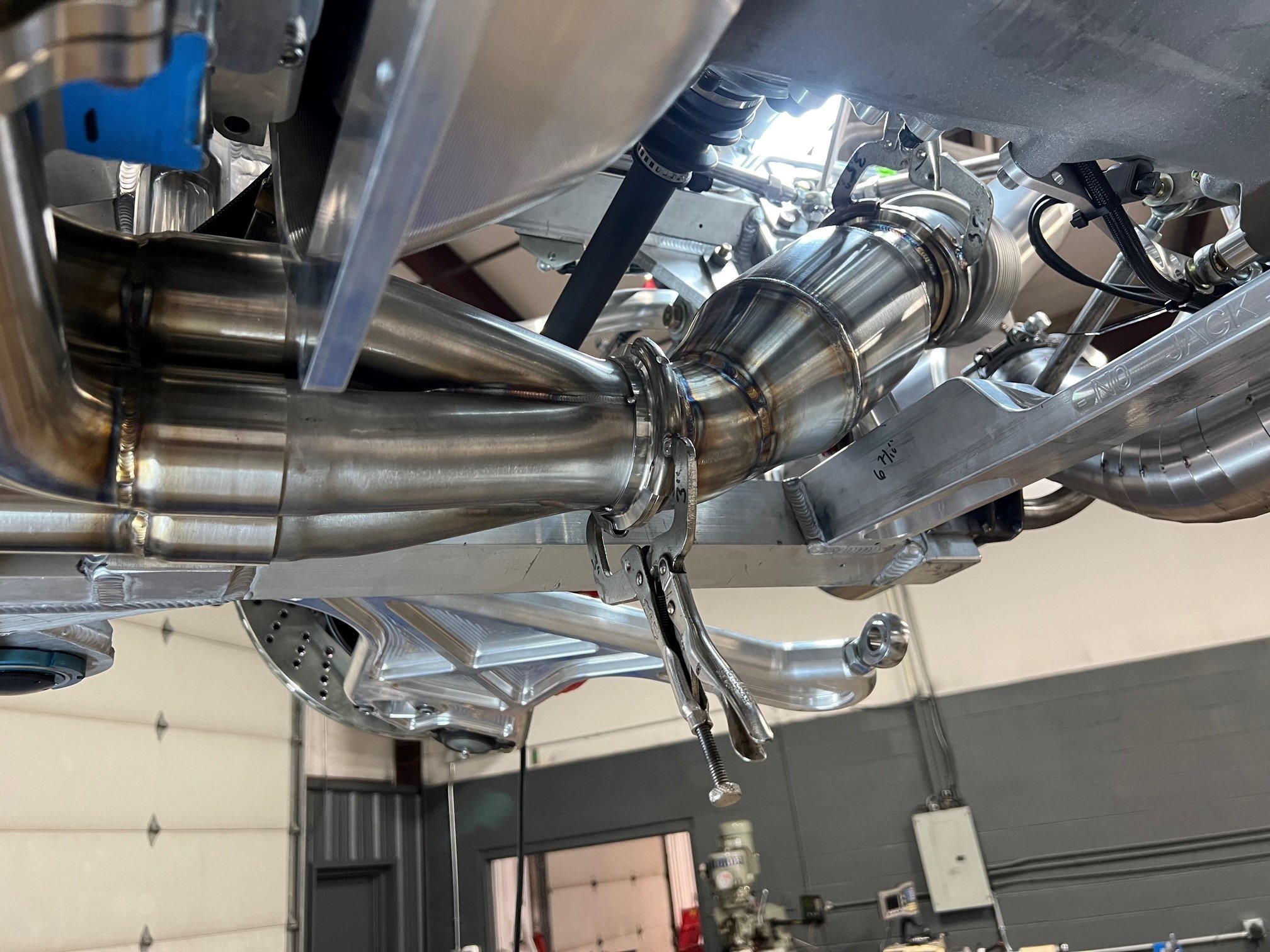
Transaxle, X-Pipe AND EXHAUST CUTOUTS
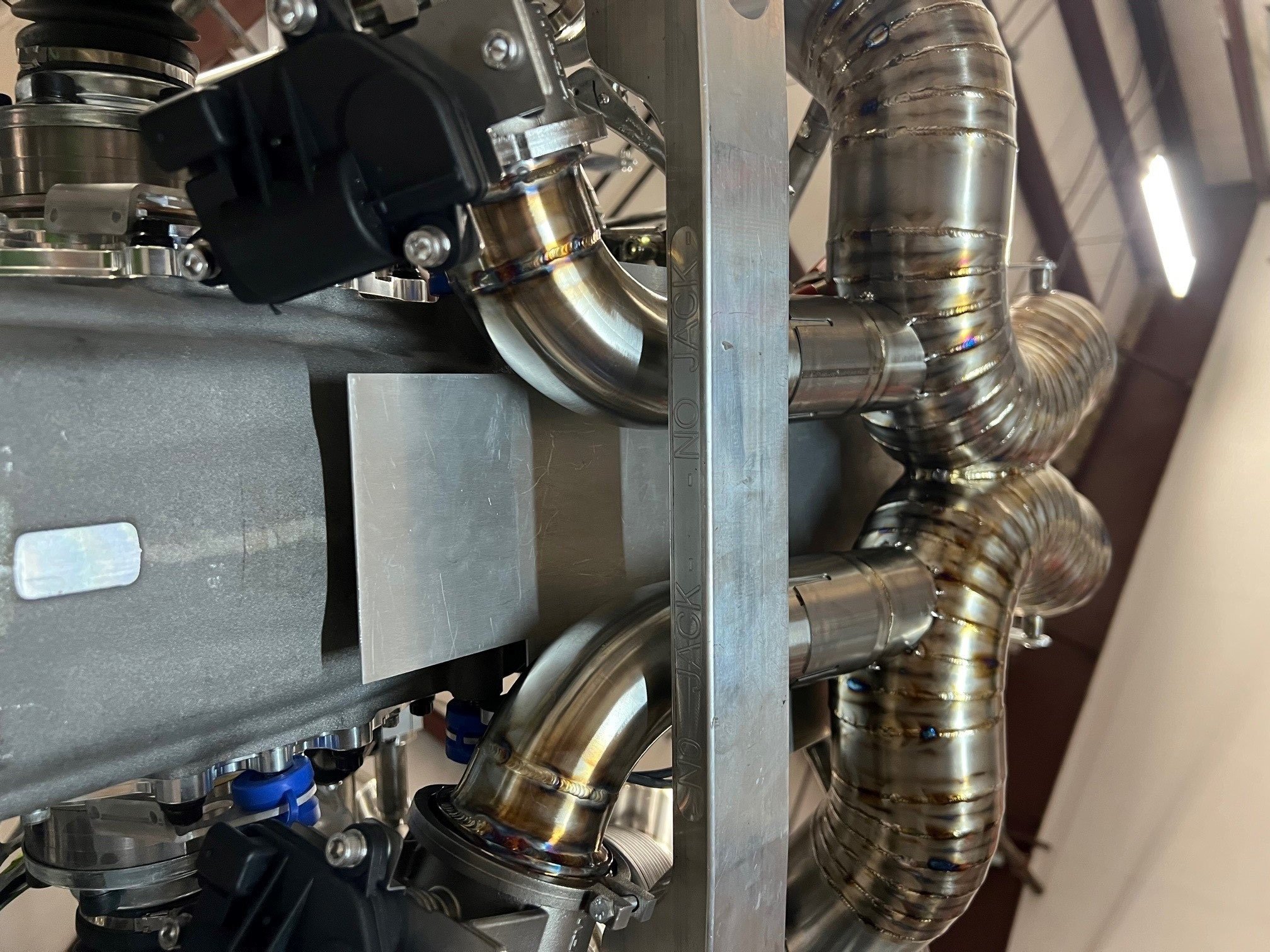
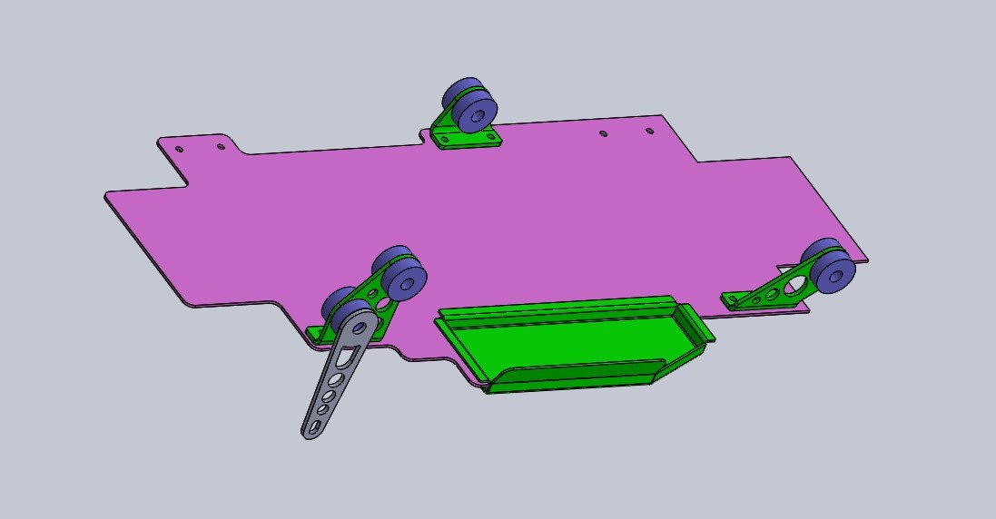
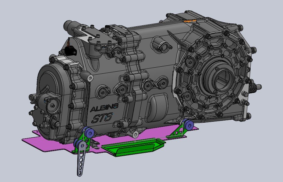
The X-Pipe and exhaust cutouts are directly under the transaxle.
I’ve been designing a heat shield, but haven’t finalized it yet. The purple is flat and the green is bent. The prototype uses screws, but the plan is to weld them.
The box structure is to accommodate the pneumatic shift servo which is my biggest concern in this area.
The prototype heat shield is laser cut and CNC bent 0.063” 5052 aluminum, but I think I’m going to use 0.030” 304 stainless steel. This could be shipped to the UK for insulation or if a more exotic material makes sense. I can send the CAD files once it’s finalized.
ENGINE Oil INLET FITTING
The fitting is very close to merge collector. I will need a shield and insulation.
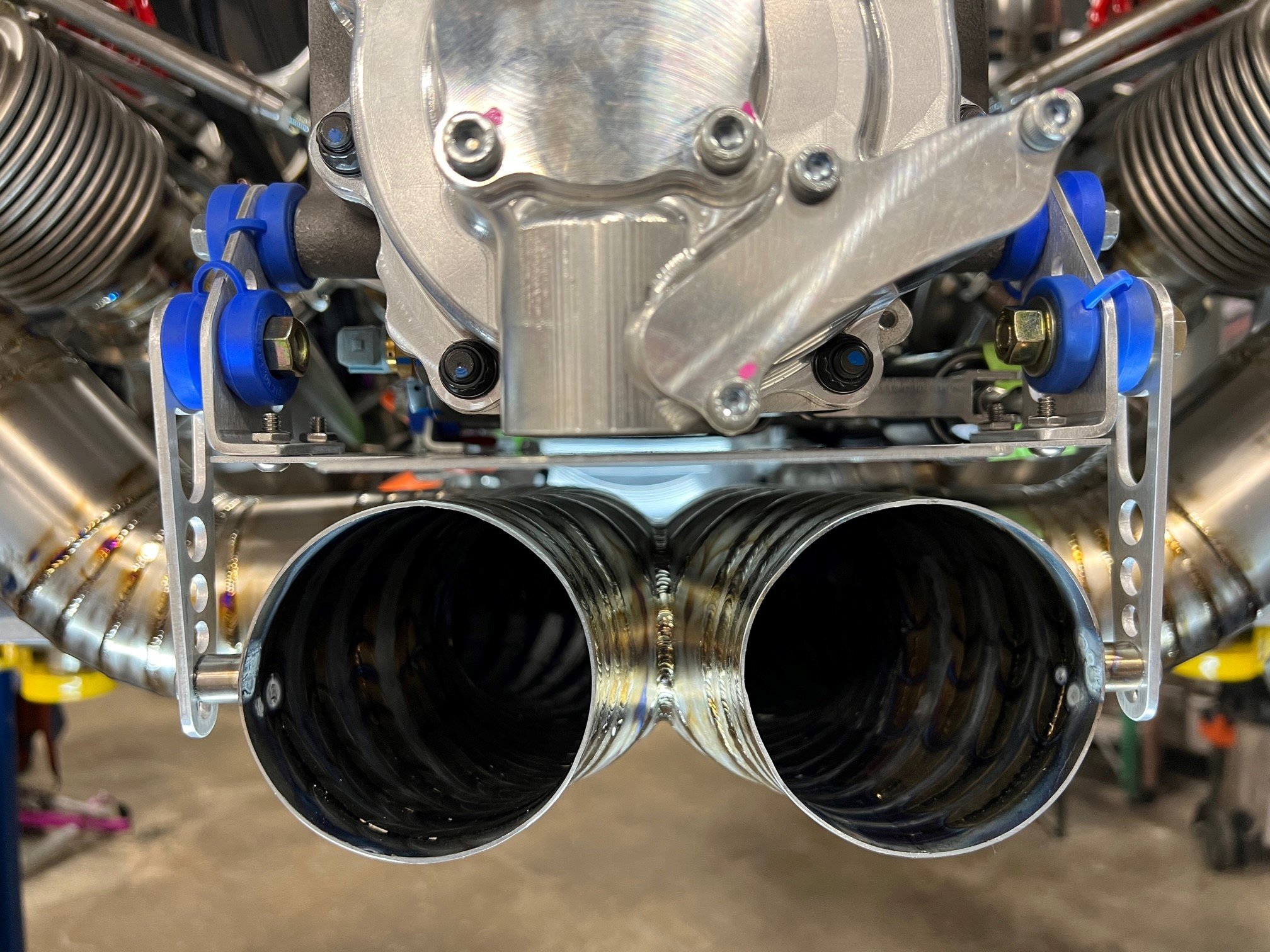
Merge Collectors and Chassis
0.25” clearance; chassis is aluminum so it will heat soak
Starter
Needs shield.
Products
I have ordered some sample ZircoFlex Foil and ZircoFlex Form
Cermaic coatings: current plan is Cerakote, but open to others. ZircoTech ThermoHold looks interesting and I ordered some samples. That said, I’m not sure I’m comfortable shipping my headers!