I’m on version three of the steering column. The new version will be custom and one of the challenges was incorporating a steering angle sensor. MoTeC makes a nice kit that uses a cogged belt to rotate a ten-turn potentiometer, but it requires fabrication to install.
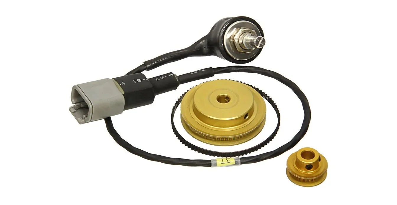
MoTeC Steering Angle Sensor Kit
The steering shaft pully has a 1/4” hole which needs to be bored to size. I didn’t have room to mount the pulley to the 3/4” shaft so I welded a spline extension to a universal joint. It has a 1” OD — any larger and I would needed a larger pulley and belt.
I’ve been doing a lot of CAD design and CAN bus configuration, so it was nice to manually machine something for a change. The first step was to refresh my memory on boring on the lathe. I’ve found Blondiehacks to have excellent video tutorials for the home machinist. Here’s her video on boring; Metal Lathe Tutorial 22 : Boring! Boring BARS, that is!
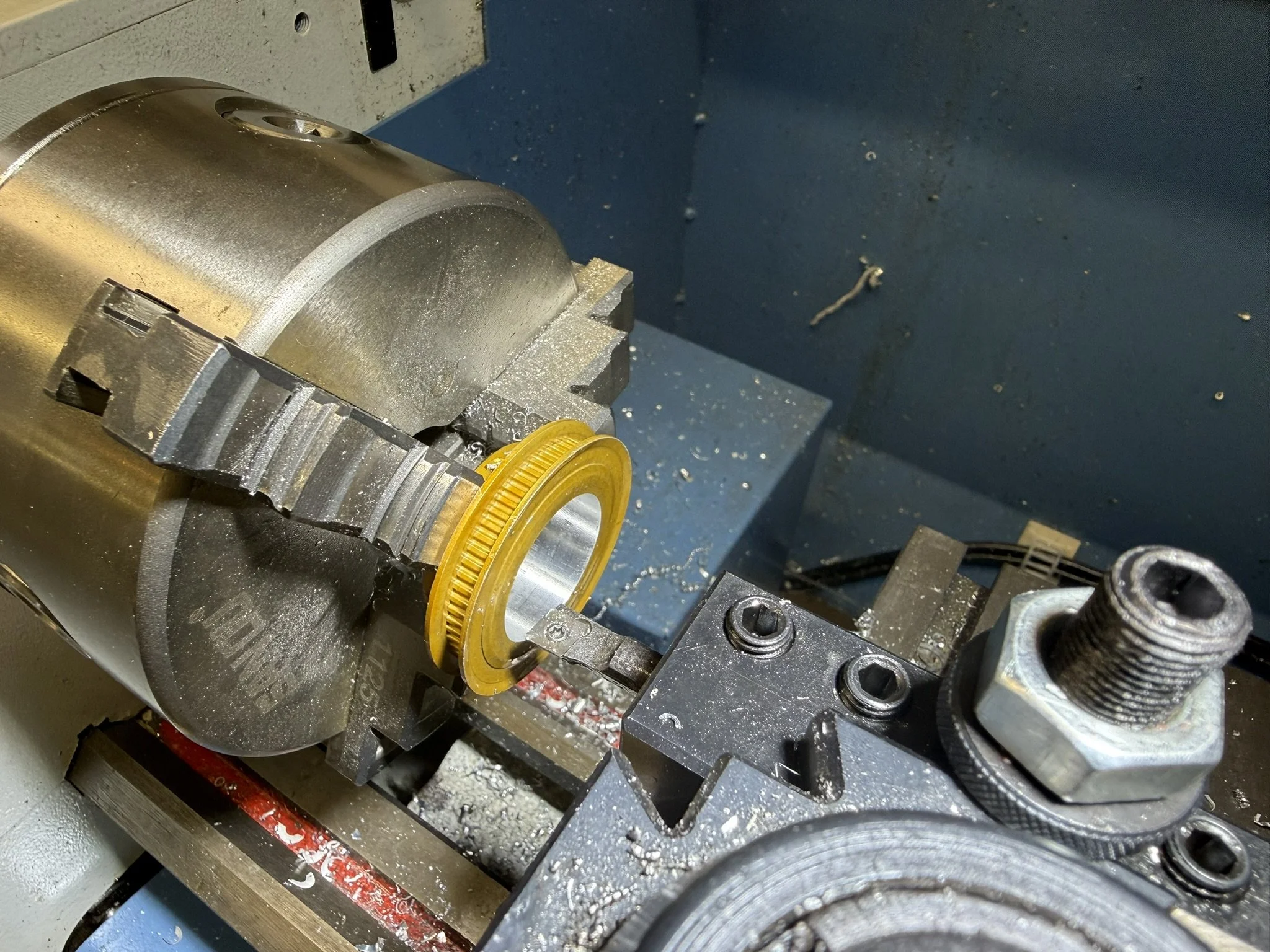
Pully ID bored to one inch
The first step was to secure the pulley in the jaw. To ensure that it was concentric, I loaded a live center in the tailstock and used it to apply pressure to the pully before tightening it. I then enlarged the 1/4” hole with a 3/8” drill bit and then a 1/2” drill bit to provide clearance for the boring bar. I followed Blondie’s setup recommendations and it was like cutting butter, no chatter and perfect long shavings. Yeah, it’s a shallow through hole in aluminum and I was only taking 20 thousands from each side (40 total) for the roughing cuts, but it was a relaxing and rewarding change of pace.
The primary design criteria for the mounting brackets were: (1) reliability — steering angle is a critical input to the traction control algorithm, (2) the ability to set everything up on the bench and (3) allow the belt to be tensioned or replaced with a single tool without needing to remove anything. I hate working in the cramped footbox, so the serviceability requirements were important. I already had a custom billet bracket that mounts the EPAS to the underside of the footbox so it made sense to design a sensor mounting plate that attaches to it. The plate has slots which enable the belt to be easily tensioned or replaced by sliding the potentiometer bracket.
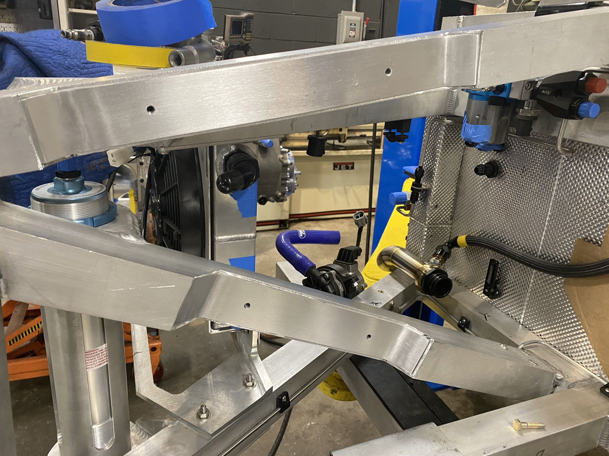
Custom billet EPAS bracket mounts the EPAS motor as close as possible to the underside of the footbox
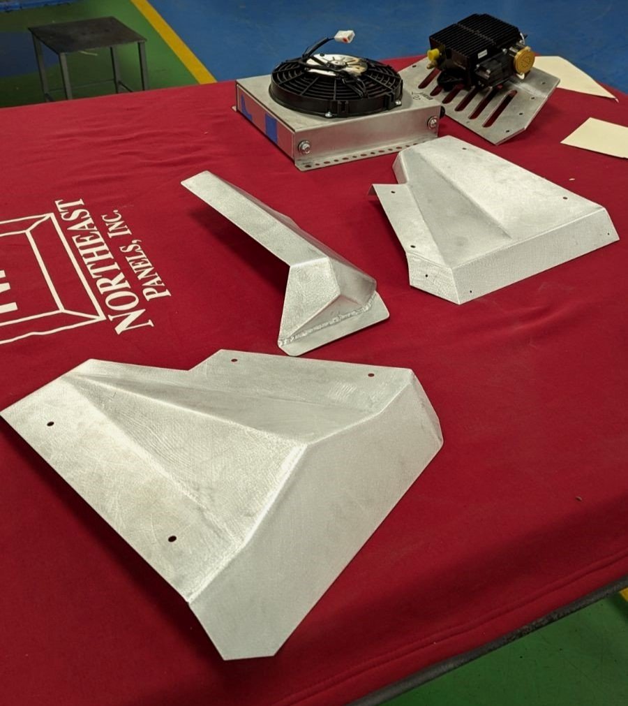
Laser-cut mounting plate and 3D-printed potentiometer bracket
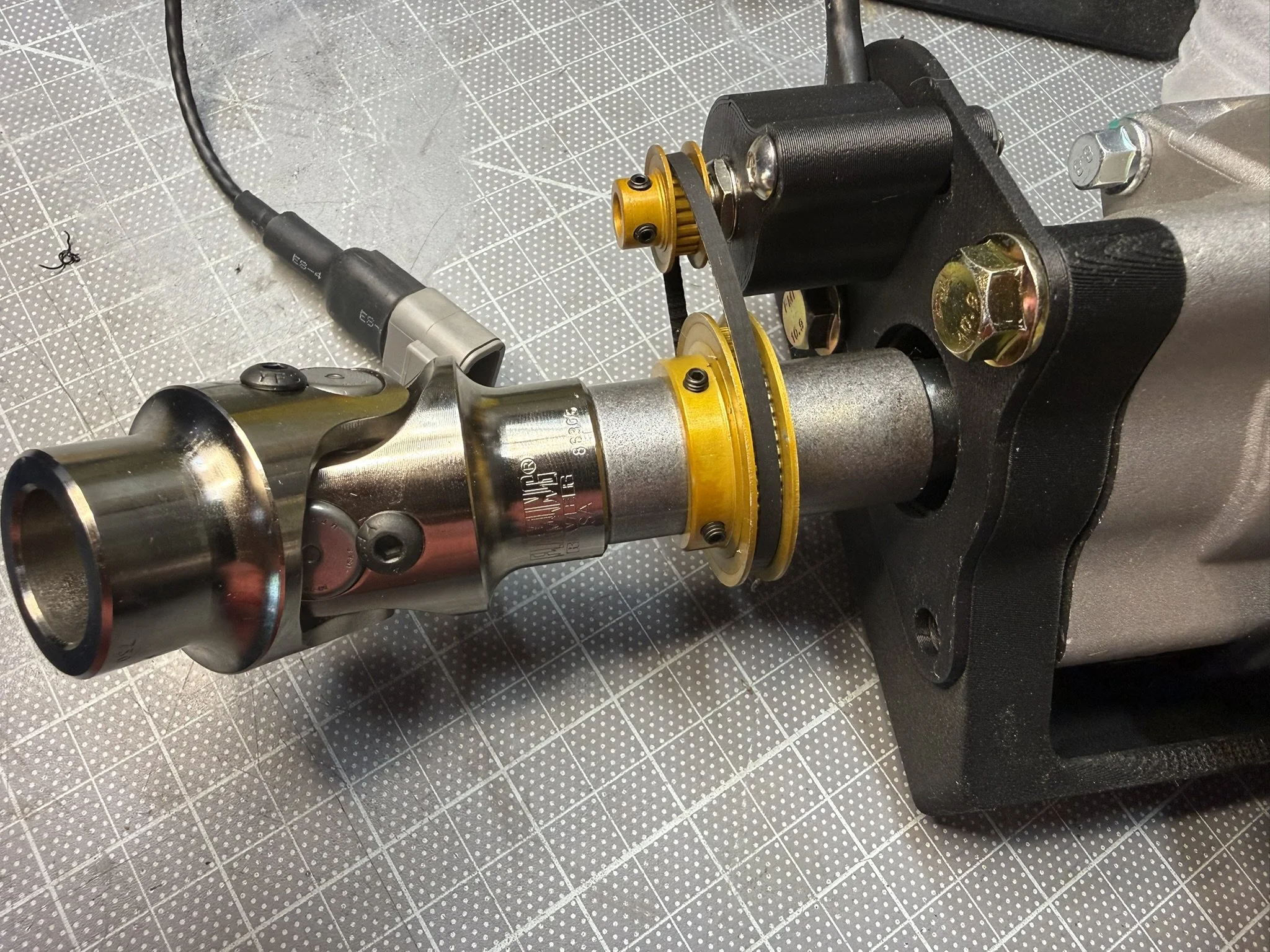
The EPAS bracket and sensor mounting plate are 3D-printed prototypes. There is a 3/4” chromoly tube that inserts into both the universal joint and the spline extension (they haven’t been welded in the picture).
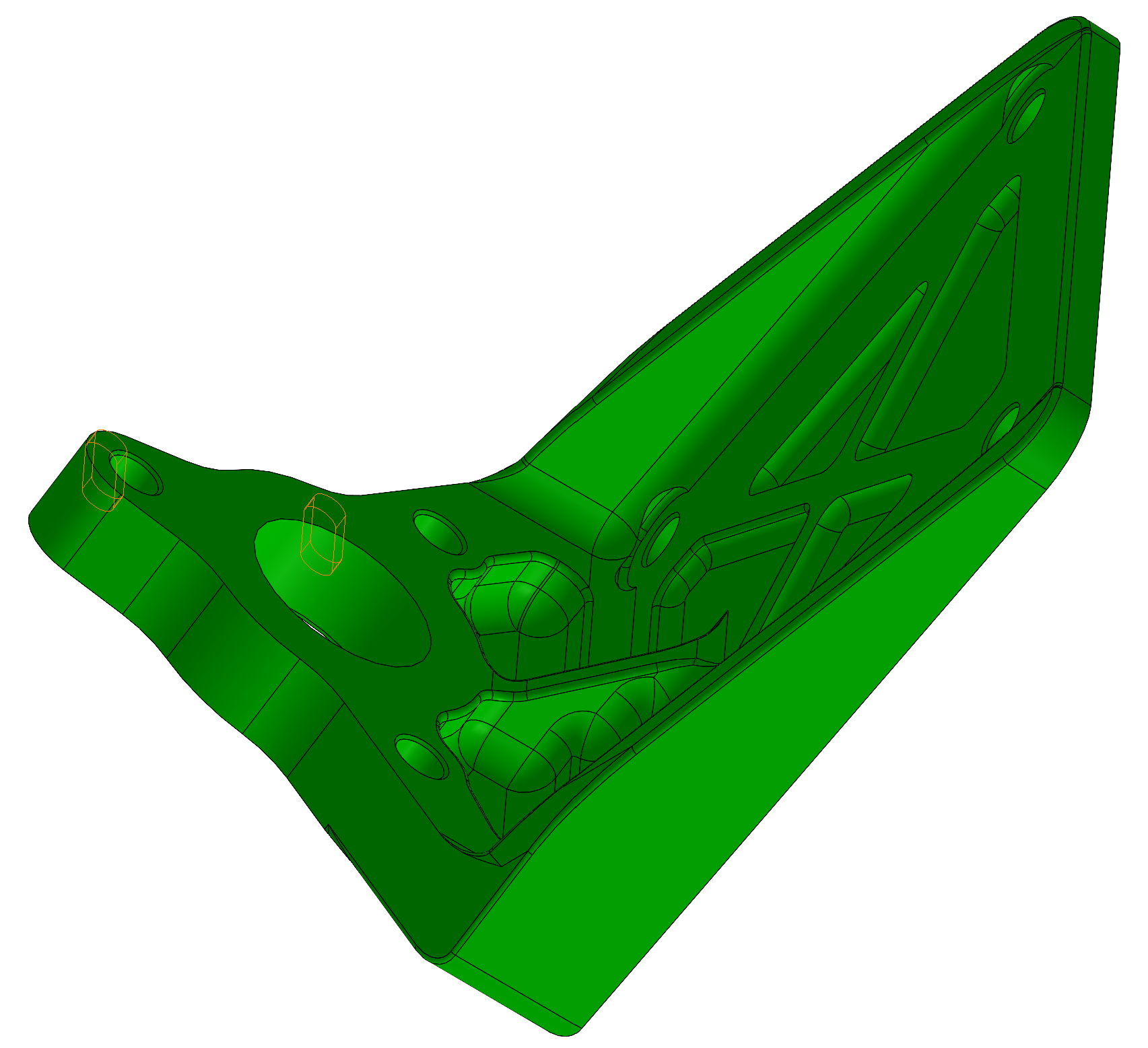
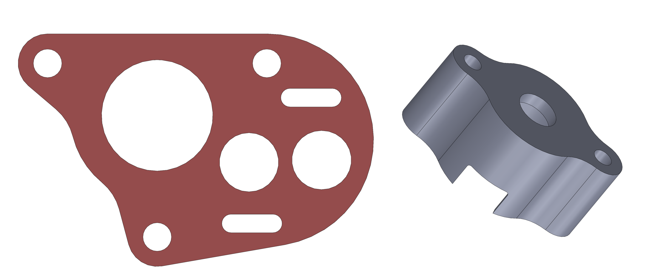
The last fabrication step was to design a locking nut plate to allow the belt to be easily serviced with a single tool. Pegasus Auto Racing Supplies is my go to for nut plates. They have better selection and pricing than McMaster. In this case, I wanted a distorted thread nut plate, but I didn’t have room for the standard ones with a rivet on both sides of the threaded hole. As can be seen below, the single-lug variant was the perfect solution (McMaster doesn’t even carry this type). These will be mounted with solid rivets which are flush on the bottom.
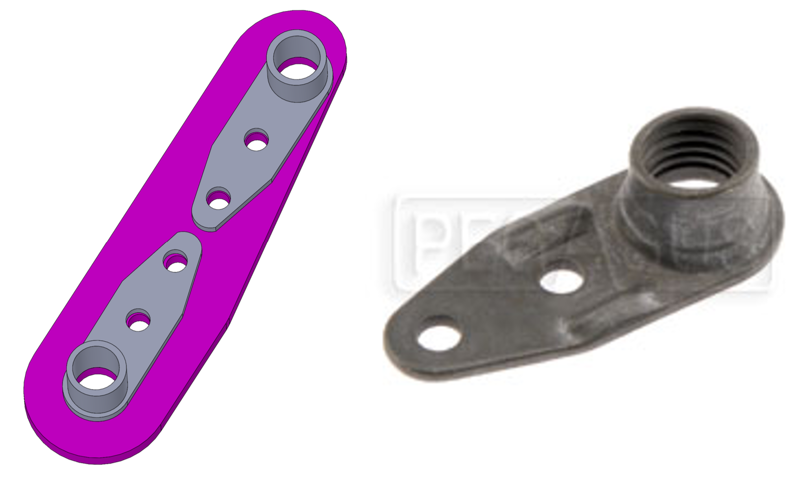
Single-lug, distorted-thread nut plate. The product photo is a different size than the modeled one.
The next step is to CNC the EPAS bracket, laser cut the sensor mounting plate and then start programming. Specifically, the sensor is wired to an input on the C187 dash so I’ll need send a CAN message to the ECU which will use it as an input to the traction control algorithm. I also need to write logic to auto cancel the turn signals.