SL-C Pictures
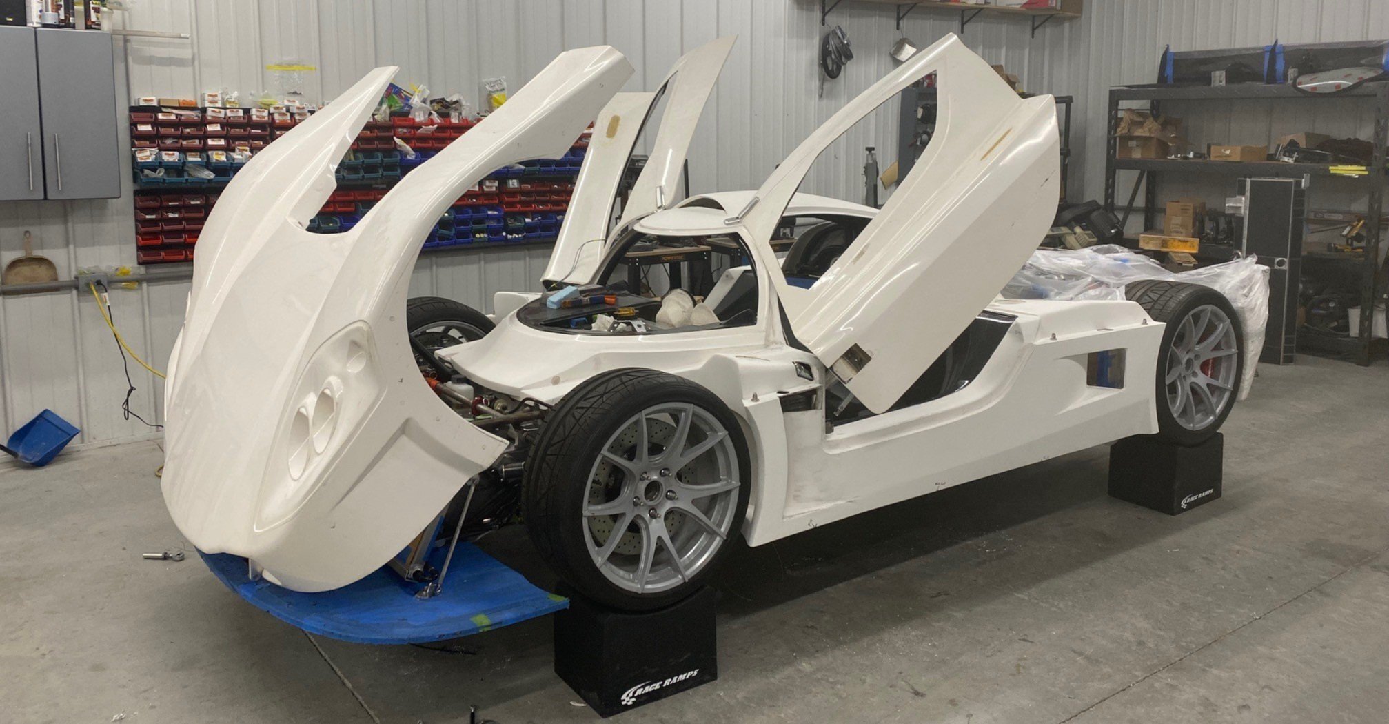
Pictures of an SL-C don’t do it justice. It makes a Lamborghini seem practical; it’s very low to the ground (your ass is less than 4” from the pavement when driving on the street) and you’re reclined at 45 degrees shifted towards the center of the car. If you look at the yellow SL-C below, you’ll note a horizontal red line that approximates the level of the driver’s eyes… lower than the side view mirror on a typical sedan.

BODY
The body is based on a 1980s Group C race car. I have lots of body mods planned and in process. The first picture is a rendering and the lower picture is the current reality. The biggest changes will be made to the rear 20% of the tail.

Chassis
The chassis a TIG-welded aluminum monocoque with a six-point DOM roll cage.

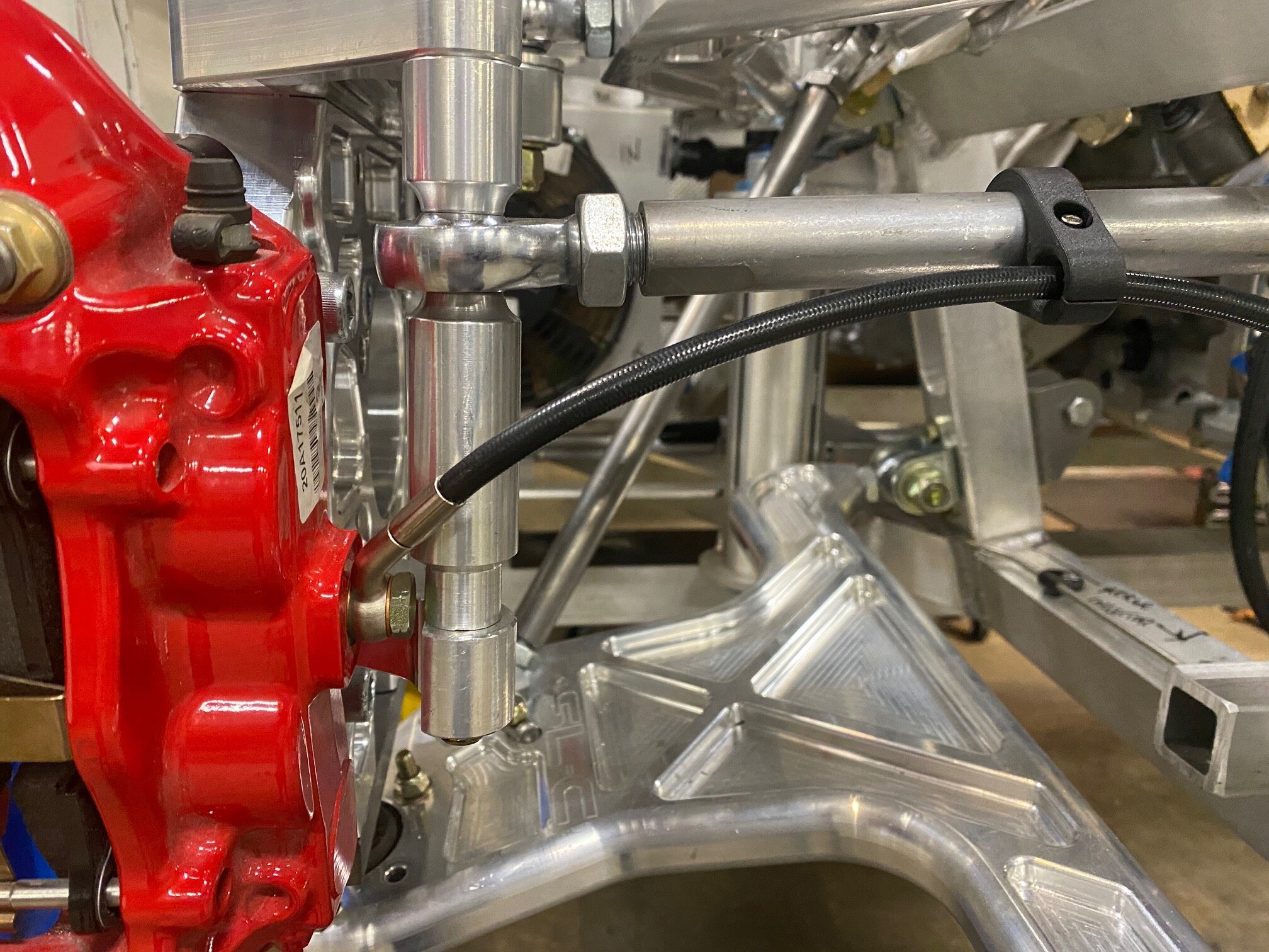
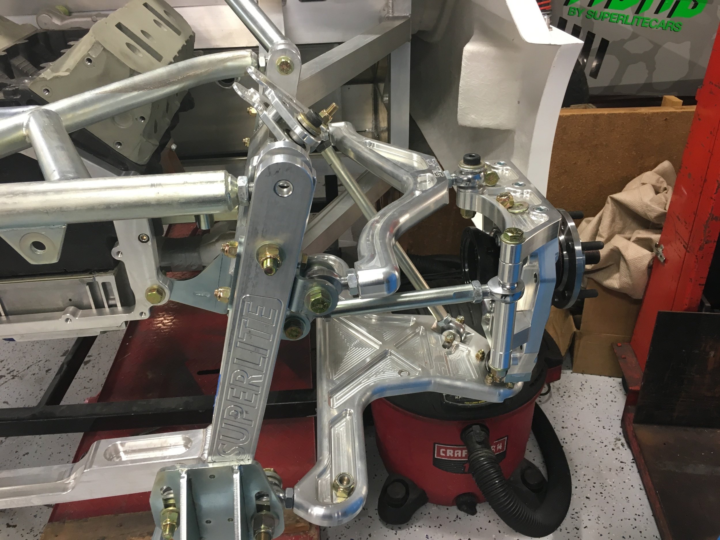
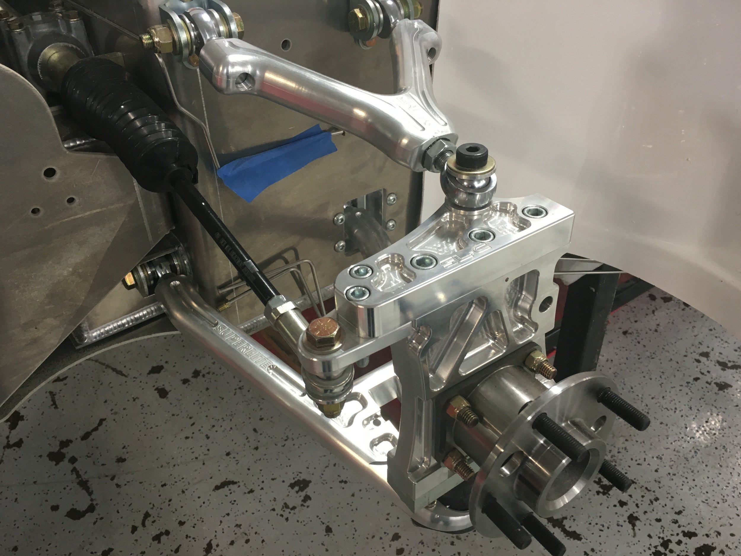
Suspension
The suspension is CNC machined aluminum. There are no donor parts and everything is connected via rod ends (i.e., no bushings!). The two videos below show the air jack system (it uses compressed nitrogen) and the cockpit-adjustable sway bars.

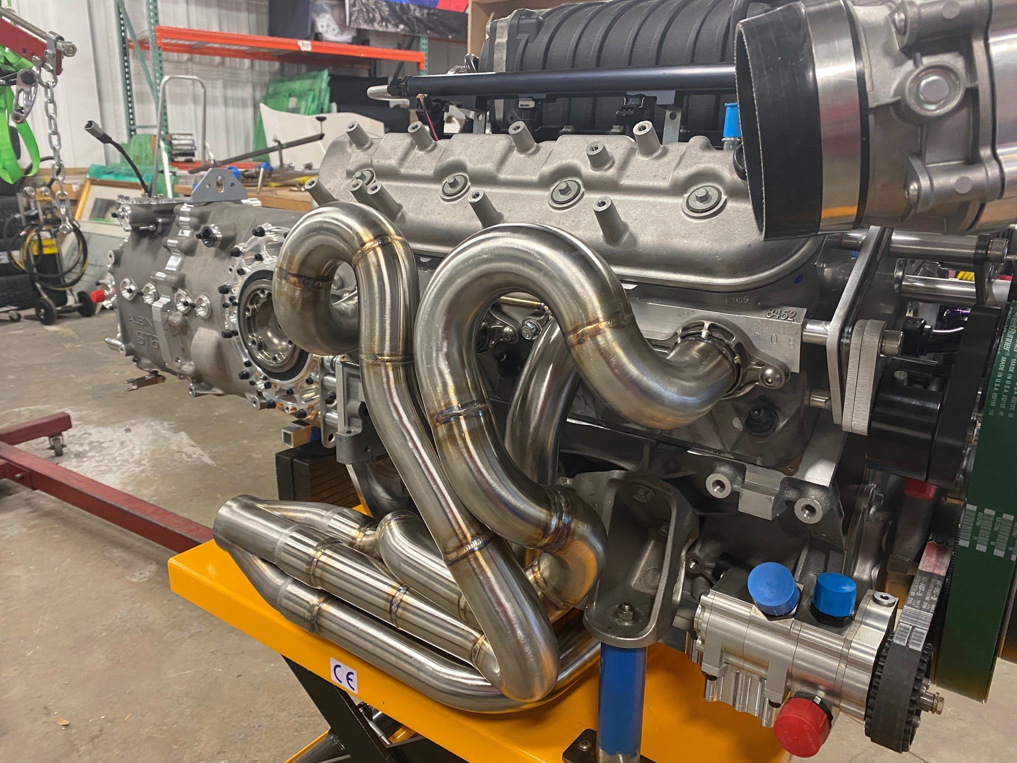
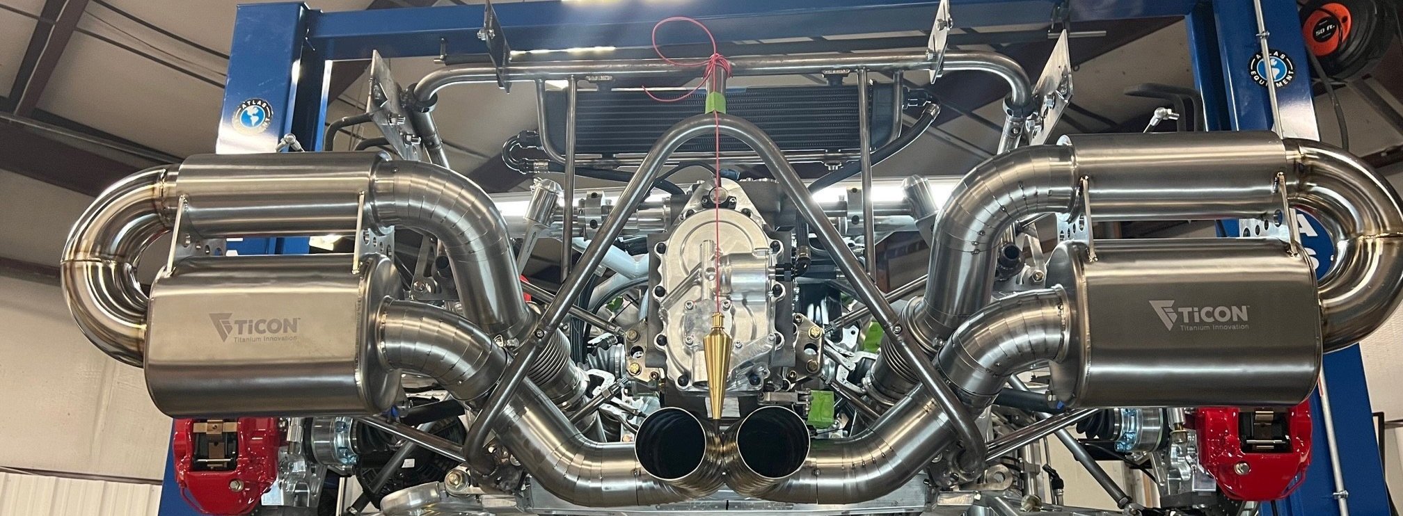
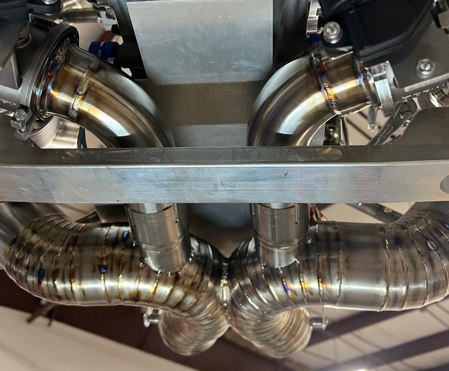
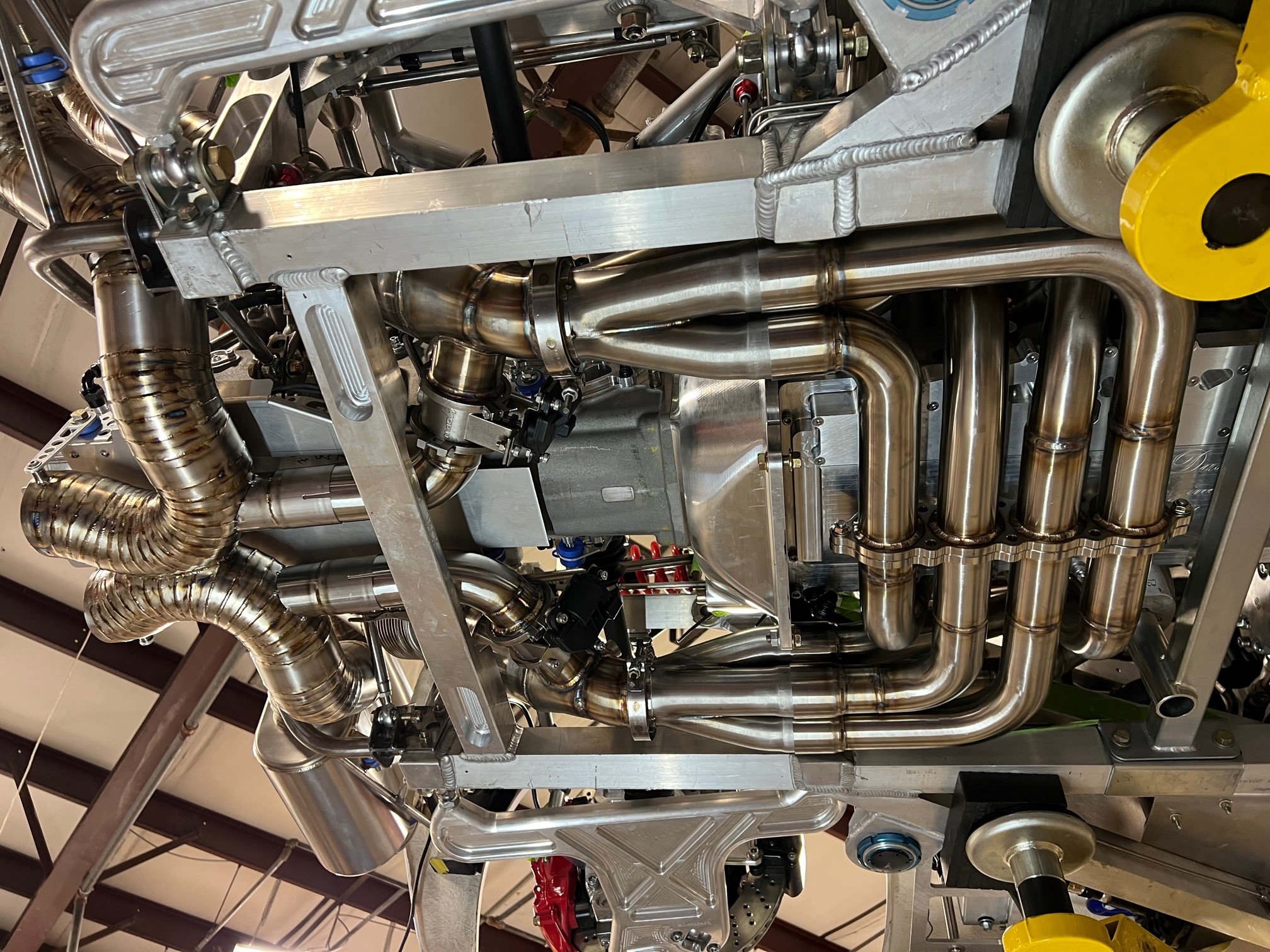
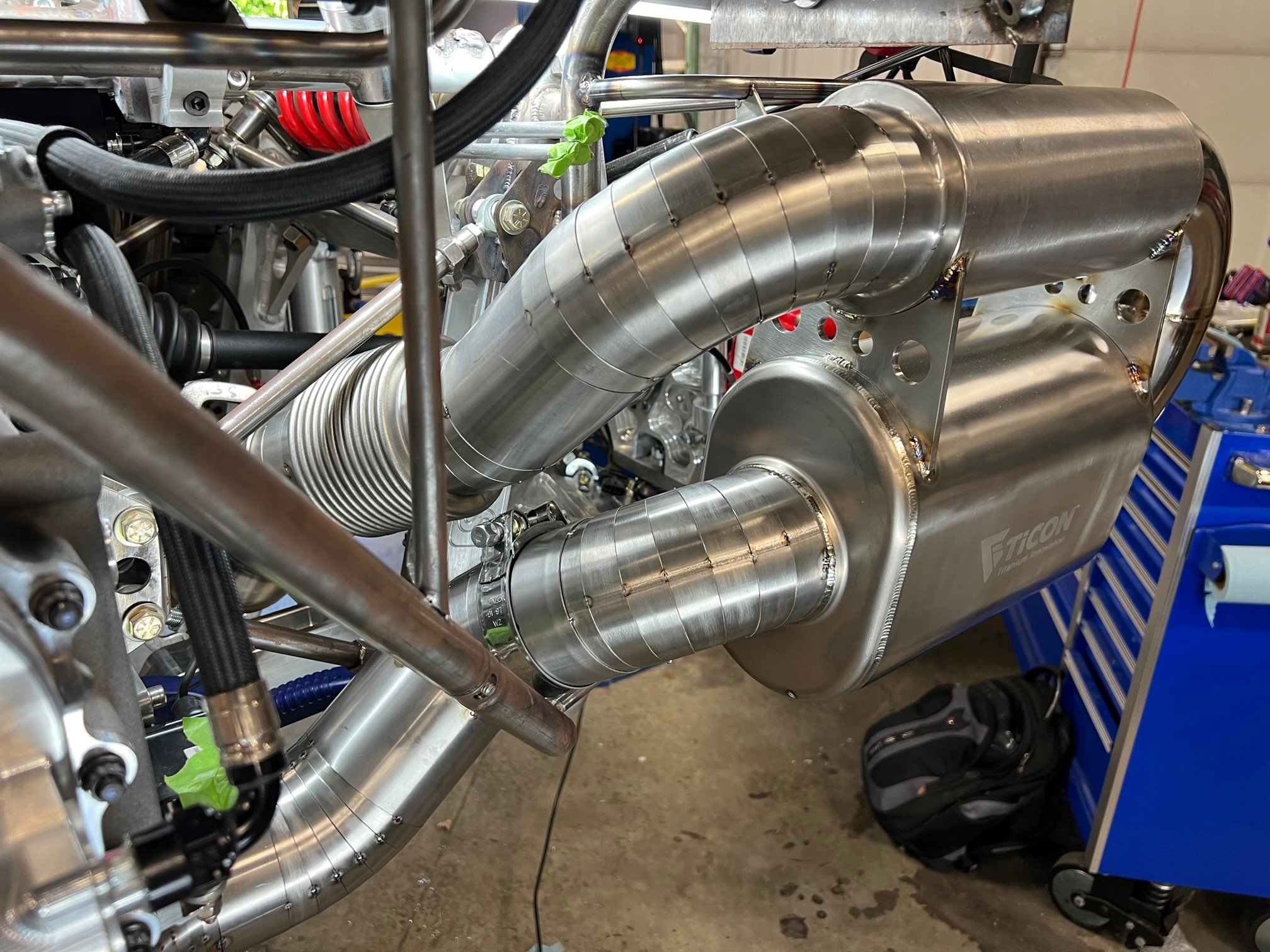
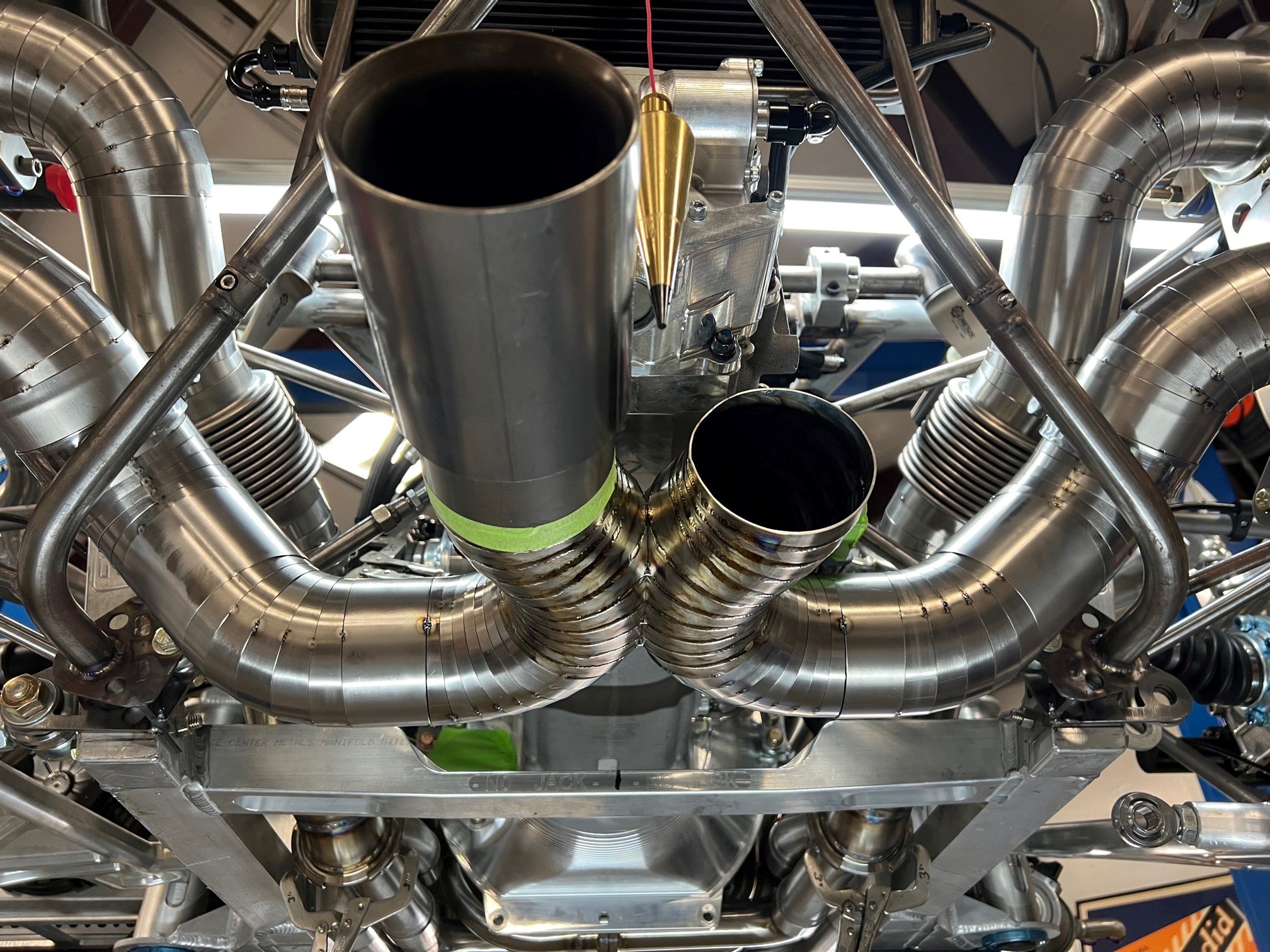
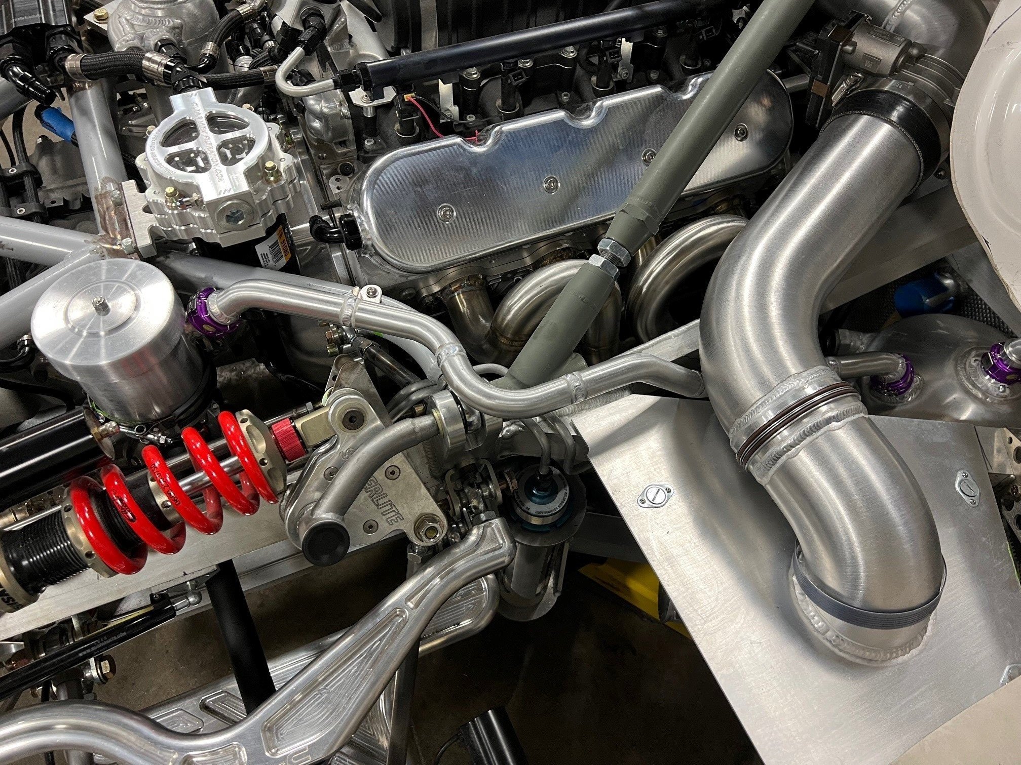
Exhaust
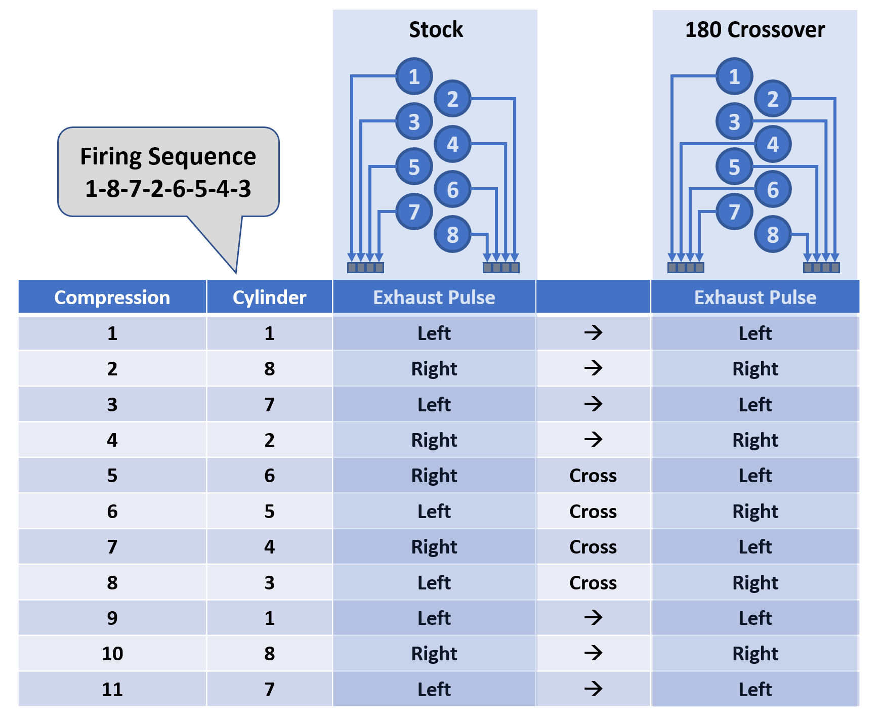
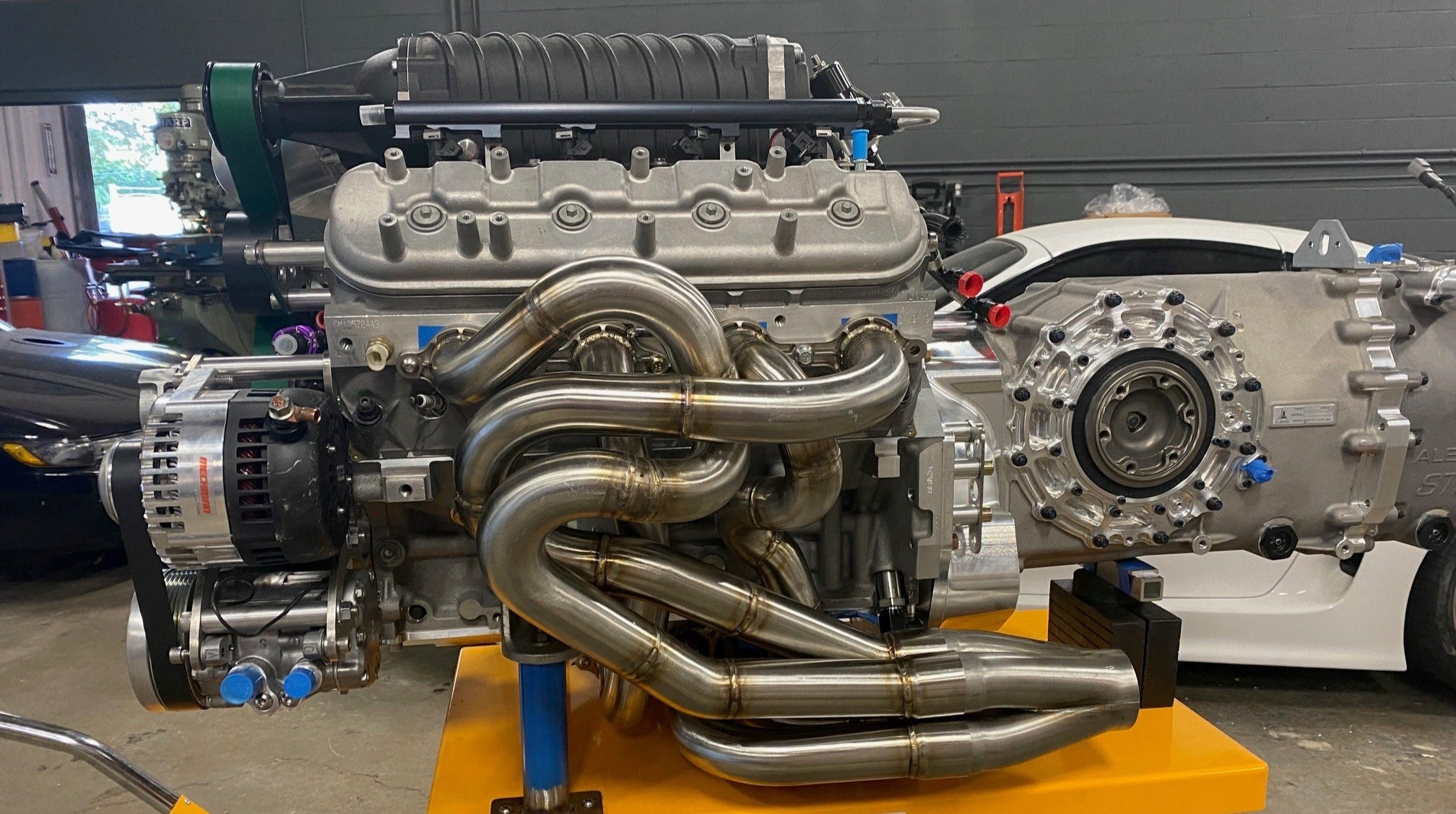
The headers are an equal length 180-degree cross over design. As can be seen in the diagram below, it crosses two of the primaries on each side of the engine to the other side to balance the exhaust pulses. This was done on the GT40s that won Le Mans to improve exhaust scavenging and power. I did it because it takes the lumpy sound out of a cross-plane V8 making it sound more like a flat plane crank. I didn’t have room to cross the primaries over the bell housing like the GT40s, so they were crossed under the dry sump.
The primaries step from 1-7/8” to 2” and are constructed from 321 stainless steel. The cat-back system is fabricated from 3.5” titanium and features cutouts and an X-Pipe. The cat-back system required 82 pie cuts, 6 mandrel bends and 4 straight sections. When V-bands, bellows, slip fittings and transition cones are taken into account there are 113 welds with a 3.5” diameter. That results in a whopping 1,242” or 103.5 feet of welding just for the titanium!
Heat shields
The exhaust system creates lots of heat management challenges. I’ll need at least 11 heat shields, one of which is shown below. It’s constructed from laser-cut and CNC bent stainless steel. It required 11 welded pieces and 22 CNC bends.


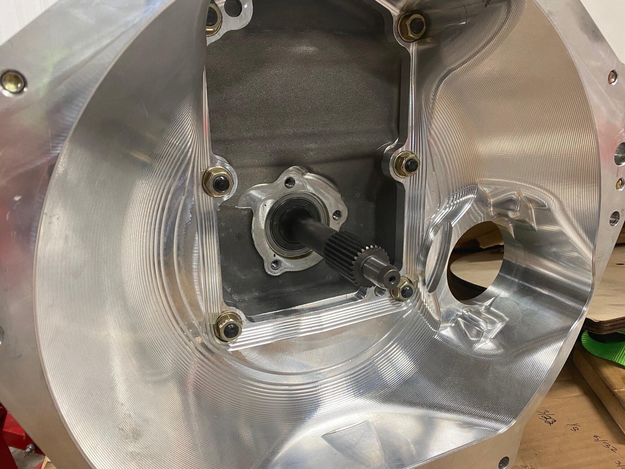
Transaxle
One of the biggest challenges with a mid-engine car is finding a transaxle that can handle the torque created by a cross-plane engine. I went with an Albins ST6-M which is a pure race solution. It has straight cut gears and a dog-box roller barrel selector mechanism which is pretty much the gold standard for gear change mechanisms in motorsports. The following video does a great job demonstrating how it works on EX-Jordan F1 gearbox. The gear change section starts at 5:15.
Dog box shifts are abrupt and require near perfect engine blipping for downshifts. I ordered a custom triple carbon-carbon clutch from RPS which, in addition to providing outstanding reliability, makes the shifts less abrupt. In addition, I used an Air Power Source (a CAN-bus-controlled pump with integrated accumulation tank) which drives a pneumatic shift servo at up to 9.8 bar (142 psi). Other features include a billet bell housing, quick-change drop gear, O-ring sealed inspection ports, etc. Paddle shifting will be managed by a MoTeC M150 with GPRP. Hopefully, the street tune will be won’t be too jarring.
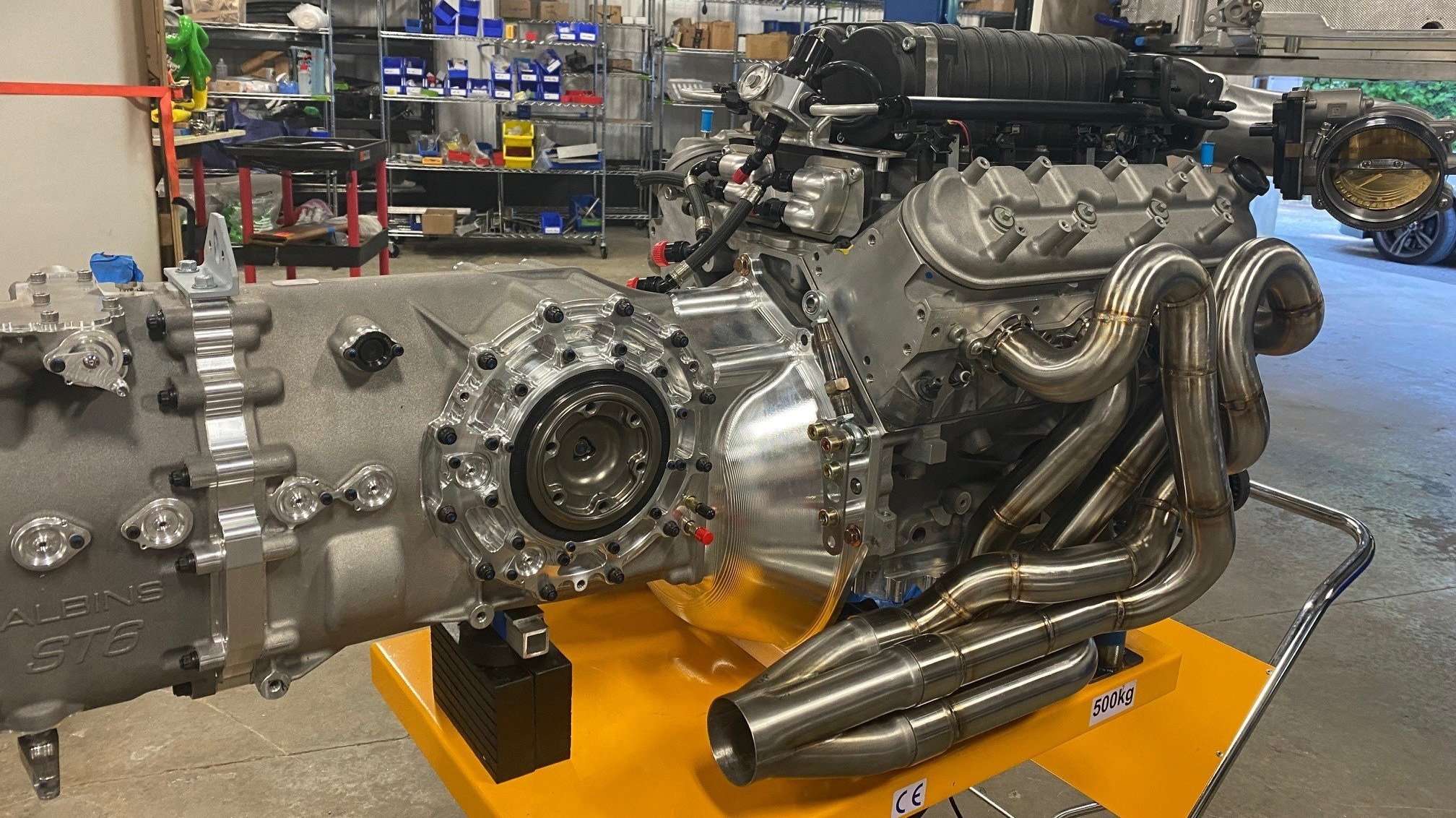

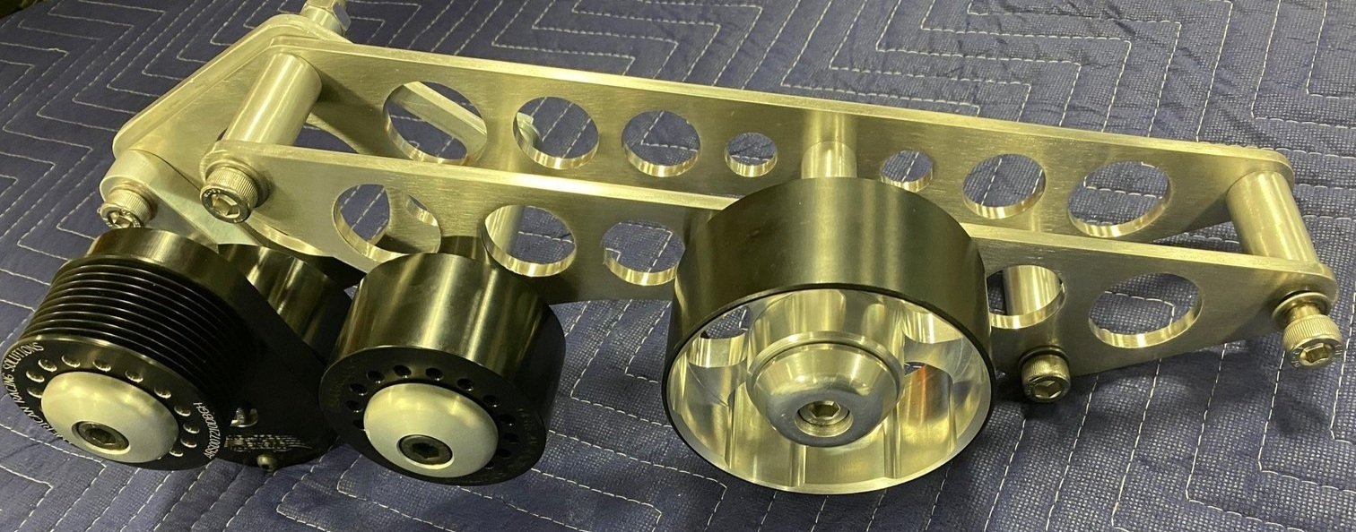
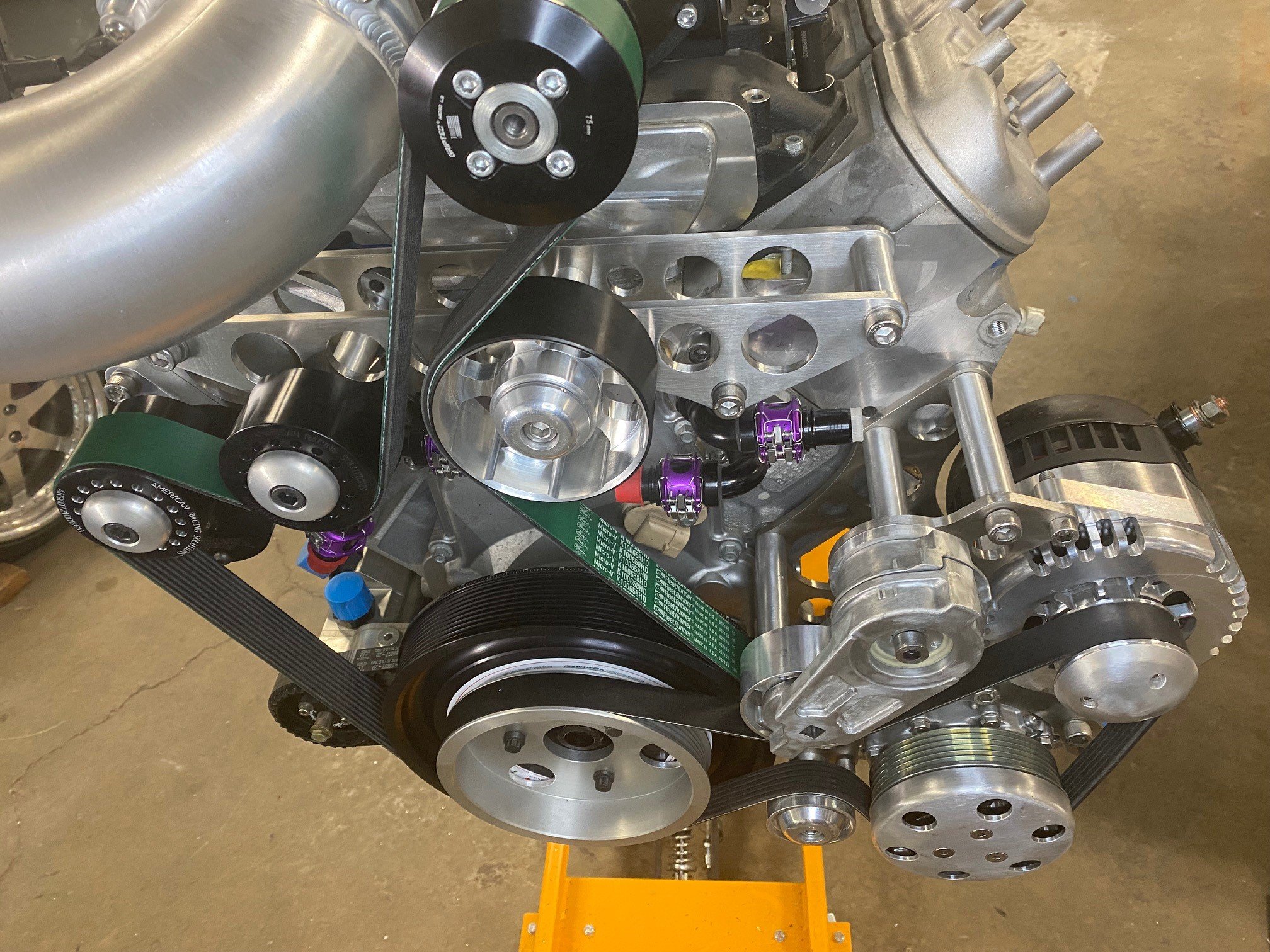
Engine
The engine was built by Brian Thompson, one of the top LS engine builders. Other than the LS7 block, pretty much everything is top-notch aftermarket (e.g., Callies billet crank, Diamond pistons, Oliver rods, Daily Engineering dry sump, etc.) The engine-dyno numbers were a little 1,000 HP on pump gas, but everything is set up for E85. It also generated over 840 lb-ft of torque at 2,000 RPM. To make room for the custom massive Superdamper, I removed the water pump and designed and fabricated the entire front dress.
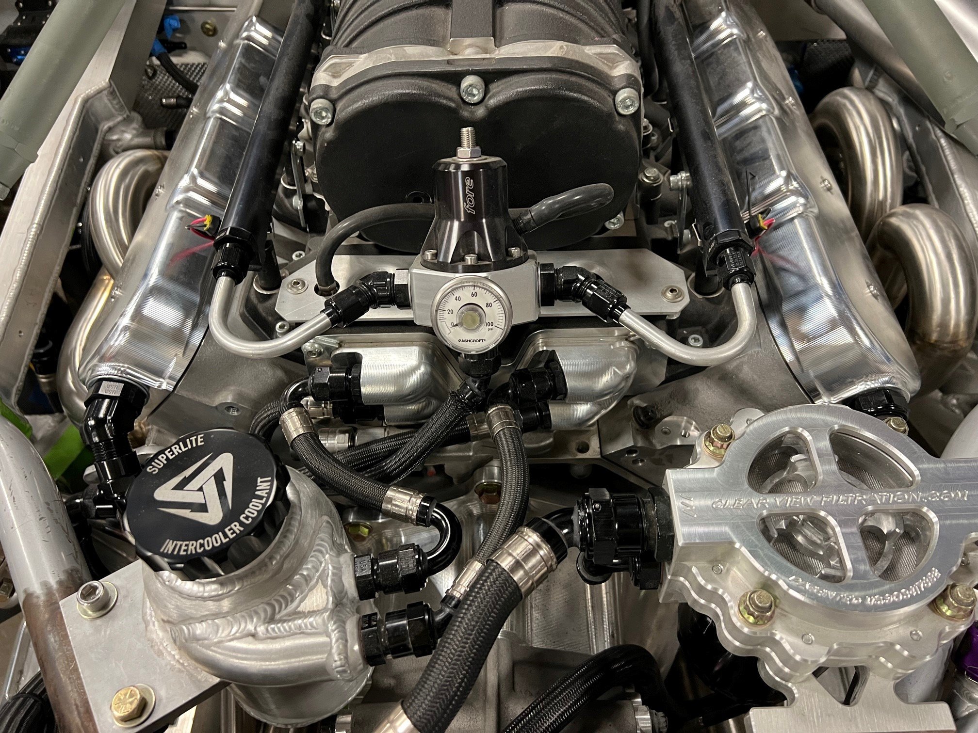
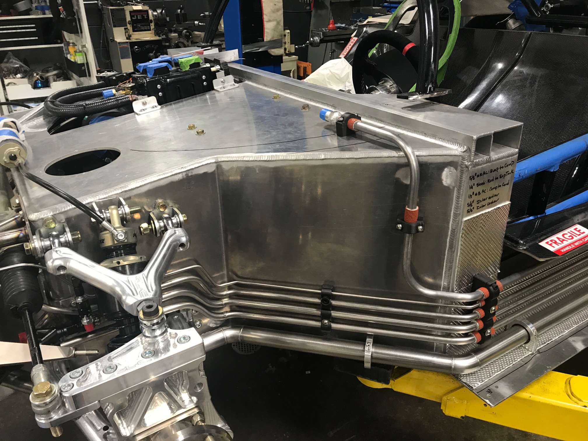
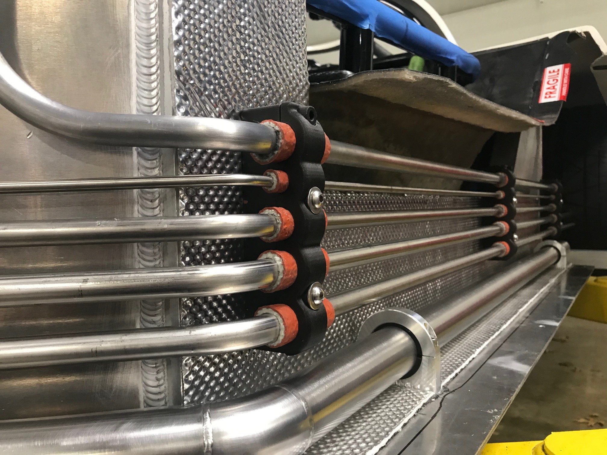
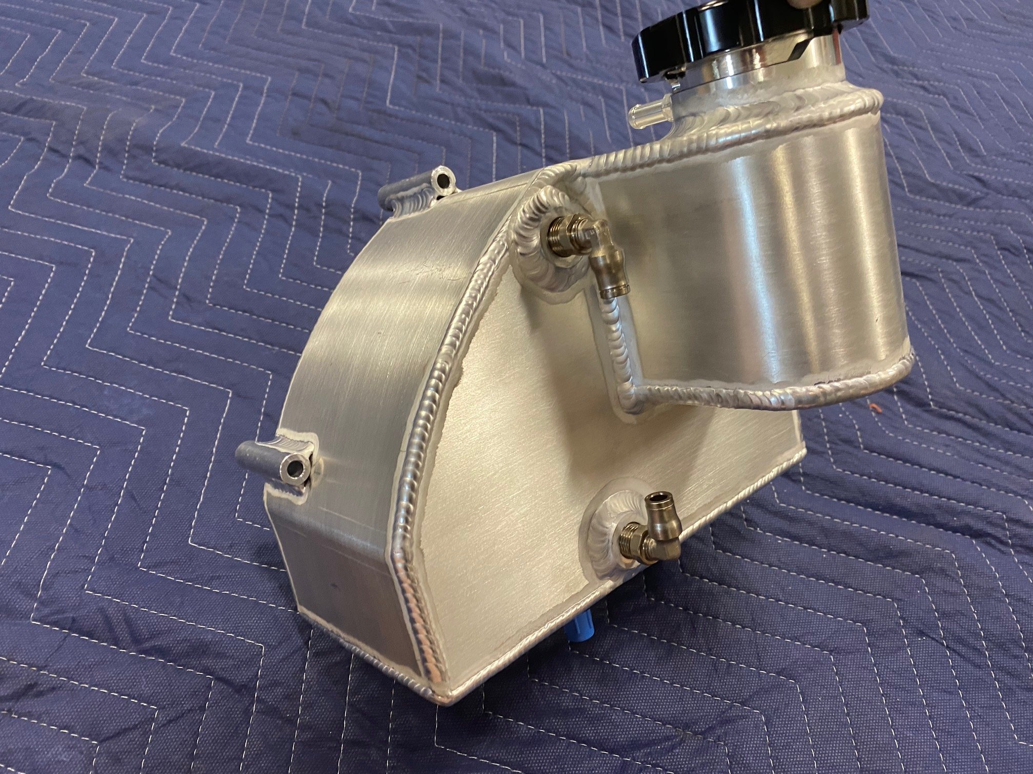
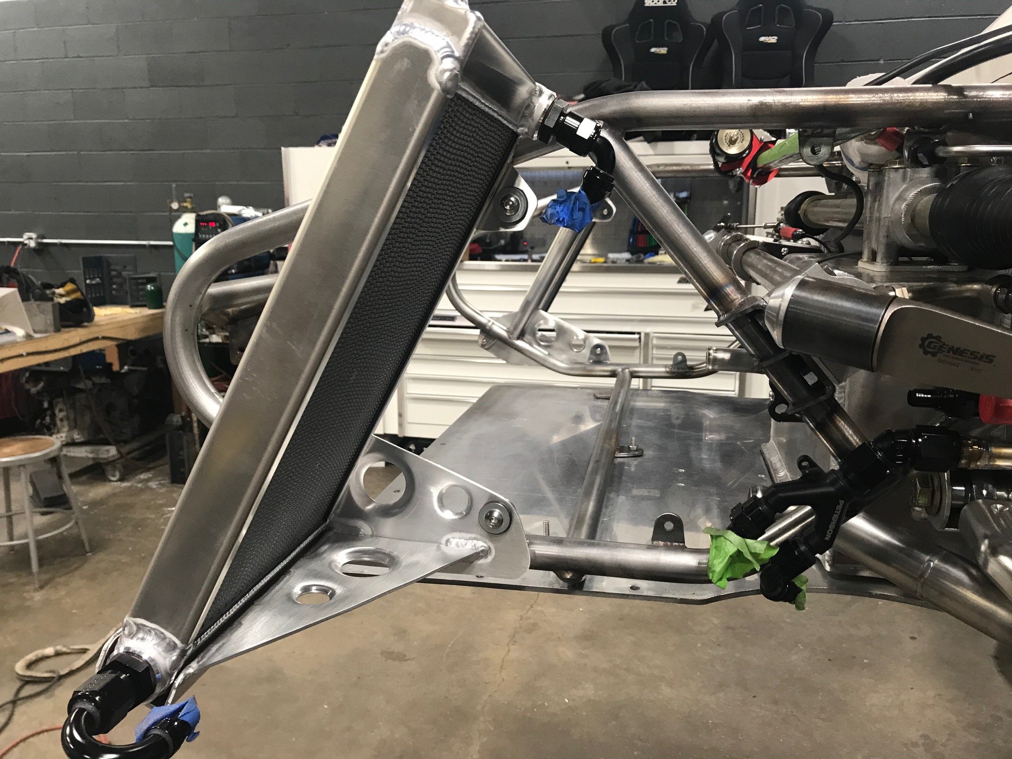
Cooling
The radiator and intercoolers were custom designed and fabricated by C&R Racing. Other custom components designed and fabricated by my me include the water pump inlet/outlet manifolds, coolant expansion tank and coolant swirl pot.


ELECTRICAL
The objective is make the electrical system as modern as possible; extensive use of CAN bus devices, solid state rather than physical fuses, custom loomed harness etc. To achieve this, MoTeC will be used extensively; C127 display, M150 ECU with GPRP, two PDM30s (30-circuit Power Distribution Module) and multiple Dual Half Bridges (DHBs). The combination of 60 solid-state power circuits, a MSEL solid state battery isolator, CAN-bus keypads and a professional fabricating the harness should result in a clean, robust system.
INTERIOR
The shell came with a dashboard, interior tub, A-pillar covers, roof and door cards. The dashboard will be significantly modified and a console will be fabricated from scratch. That said, the console will only be 3 inches wide. The A-pillars will likely need to be scrapped, but the other parts shouldn’t require much modification. There is very little room for seats and I currently have a pair of Tillet B5 carbon fiber shells, but I’m hoping to squeeze RECARO Podium CF seats, but even with modification they might not fit.
The controls will be divided amongst the steering wheel, two CAN-bus keypads and a rotary controller. Heat, A/C and climate controls are from RestoMod Air.