Wing
Superlite Option
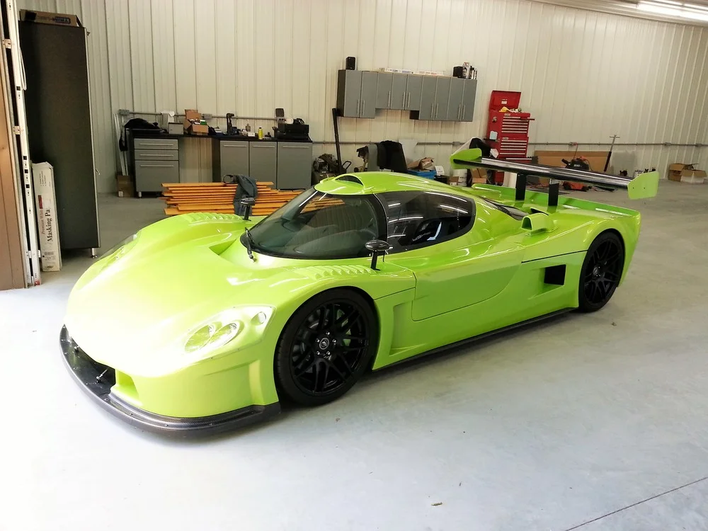
I purchased the carbon fiber wing and supports from Superlite. The wing is beautiful, but it was designed to be mounted behind the race tail as pictured in the blue car below. I have the street tail and mounting it a similar manner doesn't look right. IMO, the only real option is to put it above the tail which aesthetically overpowers the car as shown in the green car below.


Dynamic split wing
Instead, I went with the S2.Dynamic wing from Aeromotions.
While the Aeromotions implementation of a dynamic split wing is innovative and extremely well engineered, the core concepts date back to the 60's. Jim Hall was a leader in the innovation and design of spoilers, wings, and ground effects. His 1965 [validate] Chaparral 2C (pictured below) featured an innovative driver-actuated, adjustable rear wing. It was designed to lie flat for low drag on the straights and to flip up under braking. The car's clutchless semi-automatic transmission freed up the driver's left foot to operate the wing mechanism.


Chaparral 2E
By 19?? [validate], the Chaparral 2E swapped the integrated wing for one mounted on tall struts. The car looks comical to me... they sure got clean air up there, but I wonder how many bird strikes they had. In addition to activating the wing, the pedal also opened and closed the nose ducts.
The active split wing was pioneered by Nissan's R381 which won the 1968 Japanese Grand Prix. The left and right wing were independently driven by hydraulics that moved the wings up or down in order to increase cornering ability by providing more downforce on the inside wheel.
Active aero has since been banned in many racing classes including F1, but is allowed in time-attack and other categories. You have to love how engineers like the push both the performance and rule book envelope. My favorite example is the Brabham BT46B. Known as the "fan" car, it generated as much downforce standing still as it did at 180 mph.
Over the last 10 years there have been several proposals in F1 to reintroduce active aero including the use of split wings. There are also an increasing number of super cars that have active aero:
The Bugatti Veyron has a hydraulic system that varies the height and angle of attack wing as well as flaps in the diffuser.
The Huayra has sophisticated flaps located on the four corners of the car that act like ailerons on an airplane. They go well beyond providing variable downforce and acting as an air brake. The ECU takes into account steering angle, throttle position, and brake pressure, body pitch, yaw, and roll, and several other factors to independently control the surfaces at each wheel to facilitate steering.
Aeromotions Split Wing
The entire package, wing, uprights, actuators and ECU weighs only 10 pounds. It's also very compact because the teardrop-shaped uprights, called power pods, contain all of the actuators. The only connections are power and the ECU cable. The power pods are made from 6061 aluminum and are designed to act as heat sinks to keep the electronics cool. All of this results a very-clean installation for a mid-engine car. There is nothing other than the remotely mountable ECU under the tail section to get in the way or to get fried by the heat. The only installation challenge is transfering the loads generated by the pods to the chassis which is relatively straight forward given the SL-C's large rear suspension cross brace.
The wing is controlled by an small ECU which contains two high-quality accelerometers. It can be tuned via the buttons on the ECU or an optional wired remote. The ECU can store up to 10 tunes for different tracks.
The Aeromotions ECU
There are two thresholds which are set in 1/10 of a G increments:
Braking
Acceleration
There are four wing angle settings:
Braking : set for high downforce and high drag for maximum stopping power.
Cornering (Low Speed): should be set to provide the correct level of downforce needed to balance the car at the limit of traction in a turn
Cornering (High Speed):
Straightaway: is set for low drag can can be increased for more stability at high speed
The wing is nominally in the maneuvering angle. In that turn, it would be in maneuvering no matter how hard you accelerate, or corner. The maneuvering angle is set to where the car is neutral in a turn.
If you brake hard, the wing will increase downforce and drag by going into the braking angle
| Qty. | Part Number | Description | Unit Price | Ext. Price |
|---|---|---|---|---|
| 1 | S2.Dynamic | Aero Motions Dynamic Wing, Tall Option | $8,999.00 | $8,999.00 |
| 2 | ALC200-5007 | Aeroloc 50-07 Fastener, Bail Handle, Plain Holes, 0.80 | $18.77 | $37.54 |
| 2 | ALC205-1000 | Aeroloc Standard Receptacle | $4.39 | $8.78 |
| Total | $9,045.32 |
Installing the wing and ECU
Steering Wheel Control
Your ADAPT controller is set up to output wing angle. Each wing half has an analog voltage 0-5V that corresponds to wing position.
The connector on the ADAPT controller is Digikey part number RJE051880310-ND. It has the following pin out:
Not Connected
Braking
Common
Not Connected
UP
Straightaway
Maneuvering (default wing angle)
DOWN
Wing Position
The right and left servo positions are output on the 3-pin M8 connector on the ADAPT controller. The connector on the controller is Binder 99-3412-282-03.
Pin 1 is Analog Ground (Black wire on mating cable)
Pin 2 is Right Wing Half analog position output (Brown or Red wire on mating cable)
Pin 3 is Left Wing Half analog position output (Blue wire on mating cable)
Binder offers several mating cables (77-3405-0000-50003-0500 for example). The voltages are proportional to wing position, but don't go rail to rail 0-5V. Customers usually calibrate the voltages on their data loggers based off the homing routine at powerup or by manually pushing Braking and Straightaway buttons.
Wing Design
The Aeromotions wing features a high-performance airfoil and small wing angles produce much more downforce than standard wings at the same angle. As shown in the graph below, the effect of the wing will increase with the square of speed.
Low speed handling is dominated by tires and suspension, high speed handling is dominated by aero. The crossover point is somewhat unique to each car and setup.
+++++++++
+++++++++++++++
Aero is a subtle art.
This is why the top F1 teams are able to do a few tricks and walk away from the competition (who are also very clever, driven, competitors). In our case, the top of the wing has a very gentle curve. But the magic happens on the bottom. Our wing runs the only “concave pressure recovery” system in racing. It looks like the big dipper, and is a very counter-intuitive shape. But she works marvelously. Technically, it’s optimal. A recent development in aero was the ability to use an “optimal” pressure distribution, and then have the computer reverse-solve the actual shape. So, technically, the computer figured this one out.
Why is an Accurate Wind Tunnel So Important?
Mid-level performance airfoils are very robust with respect to manufacturing defects. Think of an American V8 compared to an F1 engine. Small imbalances in piston weight don’t matter at 6,000 RPM, but they will blow your engine at 18,000 RPM. Aero is the same way. High performance airfoils are sensitive to small manufacturing defects, which is why most companies don’t use them. We went a different way. We used a high-performance foil, and then created a manufacturing process + tooling to produce extremely accurate, high-fidelity wings.
What did you Test in The Tunnel?
No two wings are exactly the same – there is a little variation in each shape. For example, when you glue the top and bottom halves together, there can be a 0.010″ variation in thickness of the trailing edge. In high-performance aero terms, this is HUGE. How much is acceptable? Well, we know exactly. We found out in the tunnel. Same the thing with the surface finish. We obsess over its smoothness. How much roughness is acceptable on that airfoil, we found out. The list goes on. The bottom line is that Aero is very complex. There are a huge number of factors that need to come together to get it right. This is why F1 is dominated by aero, and why they built $42M wind tunnels to develop exotic aero packages. I promise you, the 2D airfoil on the back of the Ferrari F1 car is one of the most advanced shapes, and best understood wings, ever made. It looks deceptively simple. But it’s not."
+++++The computer uses inertial sensors, and the vehicle speed from the VSS sensor. More on this if you're interested.
Why Split?
The tuning process first balances the car front to back so it is neutral in a turn. You set the maneuvering angle to achieve this balance. If you're car is balanced at a wing angle below the stall angle (max downforce position), you have more wing than you're using. In this case, we add df to the inside wheel, and take it from the outside wheel. This maintains the front to back balance, and transfers weight to the inside wheel, as some of you have noted. Look at the GTR Buttonwillow data to see the advantage of this in the Esses. There's also a nice video Buttonwillow Track Day Dec 29th! - NAGTROC - The Nissan GT-R Owners Club
+++
Good questions! The air flow in the center of the car is lower pressure, and dirtier than the airflow at the edges. Placing the uprights in the "shadow" of the cabin reduces the drag on the uprights, and keeps them from distorting the clean air on the outboard sections of the wing. The result is more downforce and less drag.
As for functionality, the wing has three basic operations. First, you dial in the maneuvering angle to get the car neutral in the turns. When you hit the brakes, the wing pops up to the breaking angle. This gives you max downforce (and some stall if you want), providing better weight balance, more drag, and ultimately more breaking g's.
When you're on a straight, as sensed by the lack of turning g's, and vehicle speed, the wing reduces angle to a low drag setting. If you hit the brakes, or start turning, the wing automatically pops back up to breaking or maneuvering angles respectively. Response time for the S wings is sub .1 sec. You can see it really well in the videos
++++++++++++++
Very good points. We're not moving a mass, so we have no effect on CoG. What we change is the pressure distribution across the wing, the Center of Pressure, CoP. Aerodynamics is linear with angle off attack, AoA. So what we add to one side, we take from another. Maintaining the same net downforce, we transfer our force vector toward the inside wheel. You can see the effectiveness of this on the Esses at Buttonwillow.
The data will be posted on our site soon, but we shared it with the GTR guys as soon as we got it. There's also a video of the telemetry comparison of the car with the wing in static mode (electronically locked out), and with the wing active. This lets you see where the active car runs on the static car.
http://www.nagtroc.org/forums/index....dpost&p=398057
So the final question really is "does the reduced overall downforce from the split wing reduce grip more than the wing is gaining though diverting downforce to the inside tire?"
I feel the only way this could be proved is by driving the split wing car in a circle such that it could maintain a speed over 60 mph but turning such that the car was at the absolute limit of grip and the change the wing behavior. It should be possible to show one way (ie going from single wing mode to split) causes the car to break traction.
This is the real trick to understanding our controller, and unfortunately, the part that is hardest to communicate. So bare with me! We run a very efficient, very high downforce wing. Set to max df on a GTR, with a HUGE front splitter, the car pushes like hell. We have to reduce df to balance the car, and keep it neutral. Otherwise it has a hard time turning.
Since we run lower than max AoA, we have more wing, more potential df, than we can use, without making the car push. So, we shift it to the inside wheel. To your point, the tire friction is not 1-1 trade, so transferring from the loaded inside wheel, to the outside wheel, would result in more net rear traction (oversteer again). Fortunately, the wing drops downforce as it splits. It's not exactly spot on, but it's really close with the center plate! We've done the 3D CFD on the GTR to tune the amount each half moves. . . the GTR guys work us hard! LOL!
Edit: Wing upright position is going to be a compromise. To get the most effect you want them as far out to the sides as possible to increase the download on the inside tire. But this increases drag as they are likely to be in the airflow. from a stability point of view you'd want the uprights mounted in the middle of each movable wing (so that the force is sent straight down the mount. From a drag point of view you want them in covered by the cock pit shadow
You picked all the hardest points! LOL. You should have left some for everyone else, LOL. If we positioned the uprights at the center of pressure for each wing half, the force would go directly down the upright, as you mentioned. However, positioning them inward, has the same net effect on the tire, but putting more load on the inboard upright, and less on the outside upright. Ie, there's a moment coupled with the force. The net is exactly the same. Put another way, and forgive me for saying this, the free body diagram of the car has the aero force vector acting on the wing, and the balancing forces acting on the tires. Since it's a rigid body, the path inbetween is inconsequential.
Wind Tunnel
Aeromotions tested their wing at the Windshear wind tunnel. The tunnel is an engineering marvel...
The high-tech rolling road is 10.5 feet wide by 29.5 feet long and is made of a continuous stainless steel belt that is just one millimeter thick. During testing, sensors under the belt measure the aerodynamic down force being applied to each tire.