Dance Floor

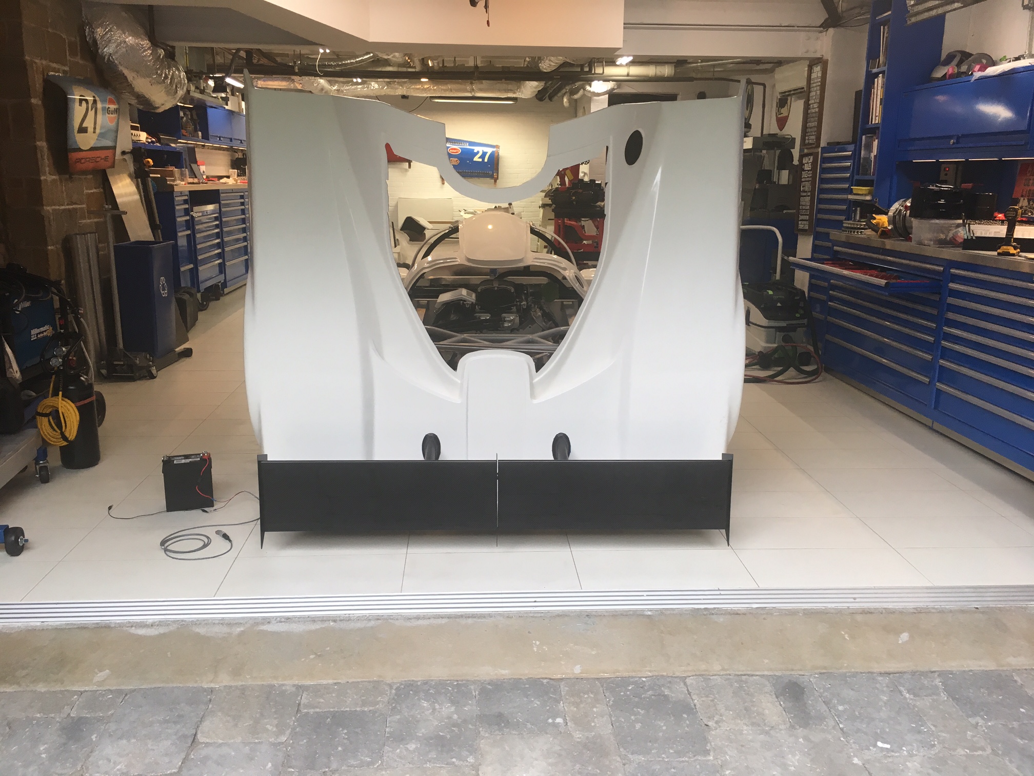
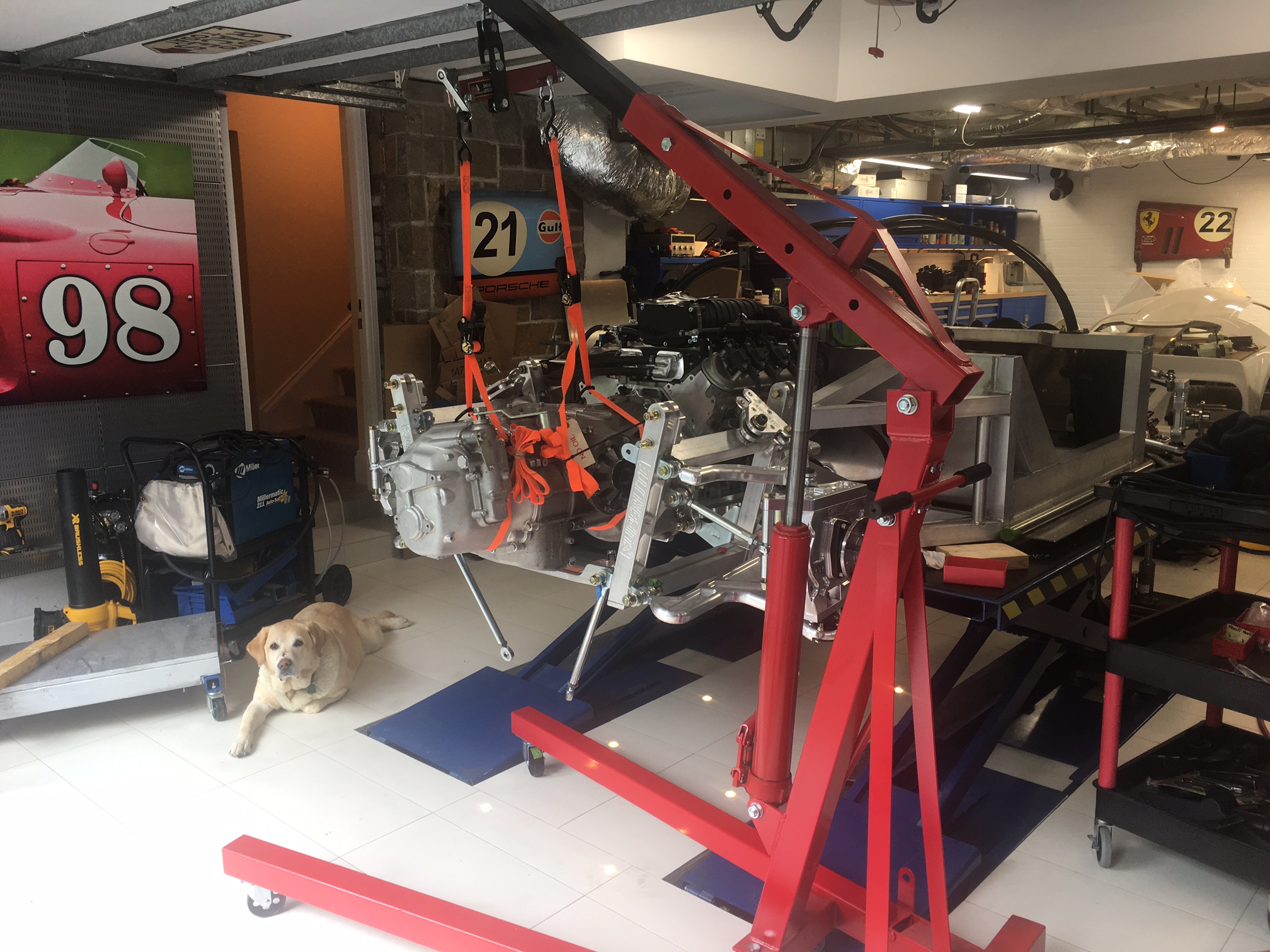
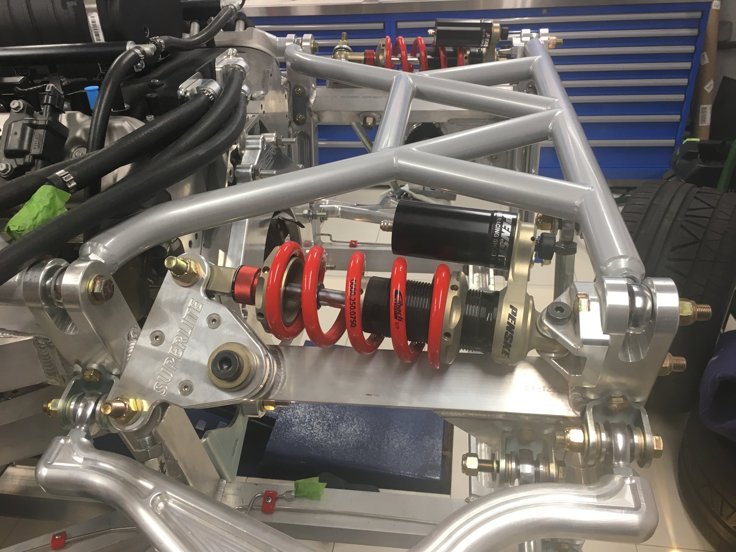
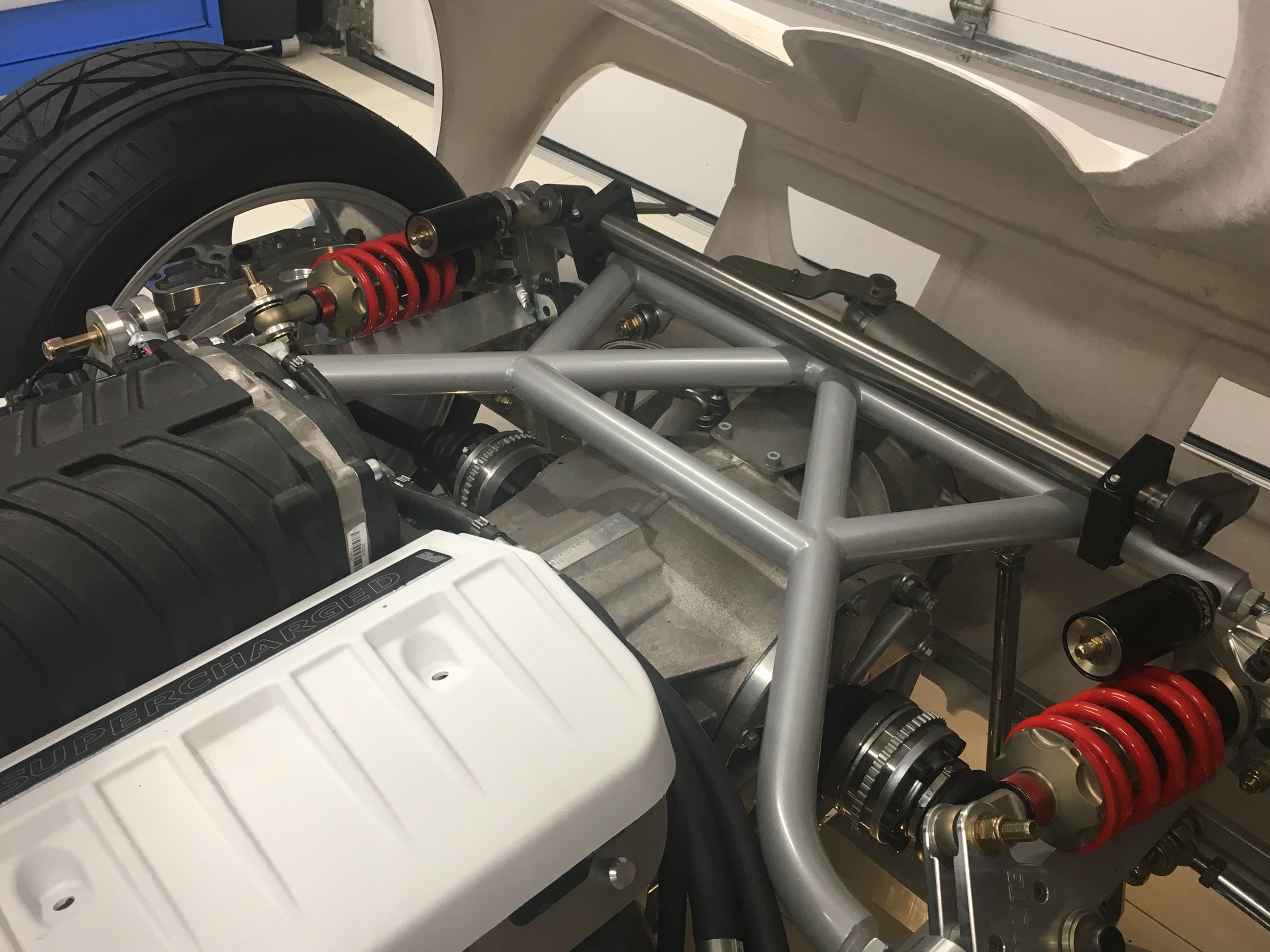
The dancing wing that I videoed in the last blog post will generate over 800 pounds of force which will crack the body. So, I need to design and build a stable dance floor. With the event of CAD, not all work on the car needs to be done in the garage so I took some photographs and quick measurements before I left for vacation.

Fortunately the rear suspension cross brace, per the SCCA rule book, is made of 1.5" x  0.125" wall Drawn Over Mandrel (DOM) steel tube which is perfect for welding brackets. The two design priorities are strength and adjustablility. Oh yeah, and it must look cool... my wing deserves just as nice a floor as Travlota had, but I think I'll skip the lights.

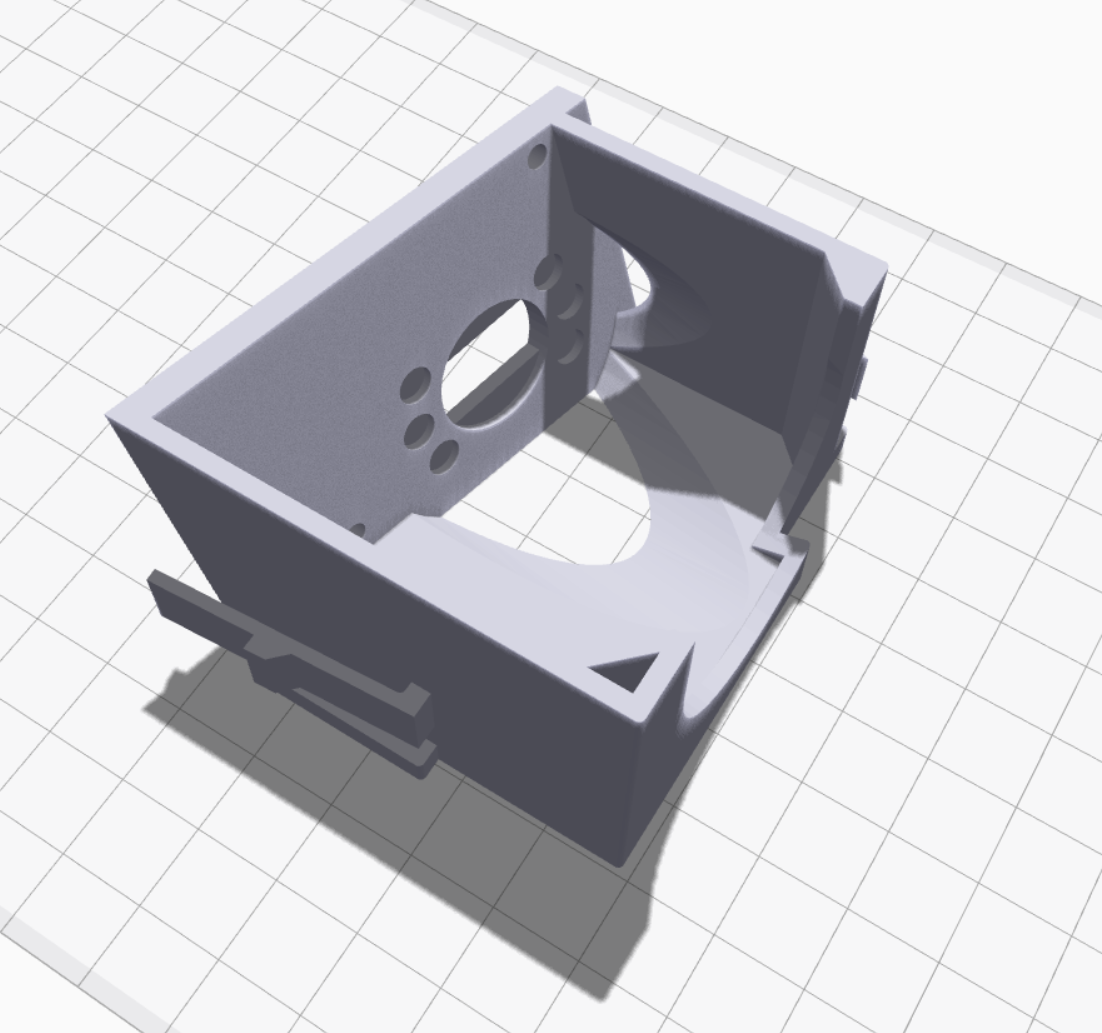
Mounting plate & cover

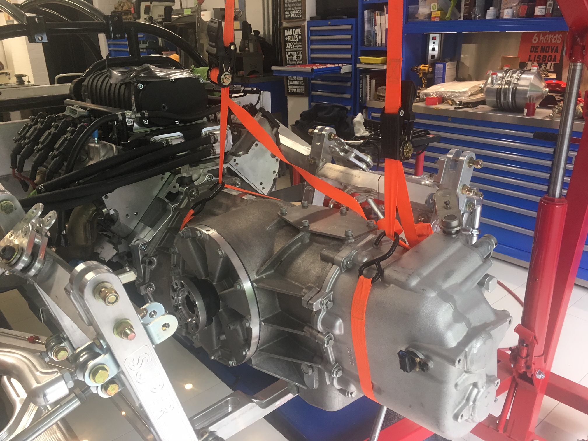
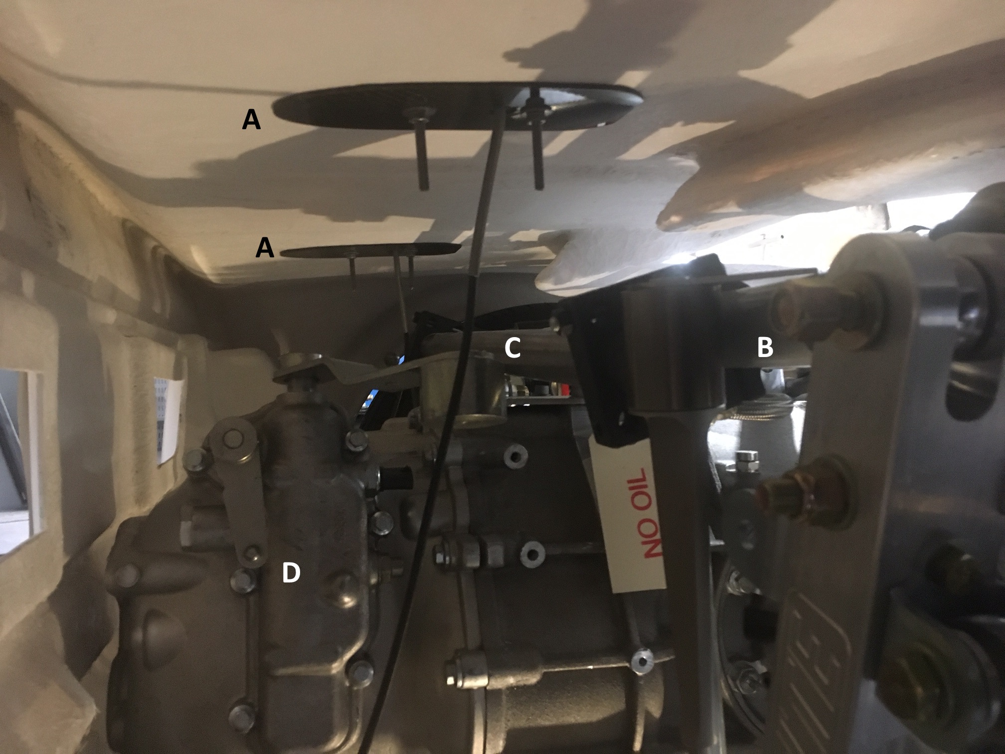
The lights built into garage floor really paid off in the picture above. The relevant parts are as follows: (A) the carbon fiber backing plates included with the wing (the long studs will be cut once the bracket is finalized), (B) the rear most tube in the rear suspension cross brace, (C) the rear sway bar (must have been drinking, because it's crooked there), and (D) the monster Ricardo transaxle.

The first piece is a mounting plate that replaces the provided carbon fiber one. It will be made of ¼" aluminum and will be bonded to the bottom of the tail. A removable cover (shown in red) with the same profile will be made of thin aluminum or stainless steel. The sole purpose of the cover is to hold the power pod wire in place.

The second piece is the bracket that will be welded. The side pieces will be made from¼" steel (that might be thicker than I need) and the cross piece will be ⅜" steel with a ⅜" threaded hole in the middle. It will be TIG welded by someone who knows what they's doing. I could MIG weld it and it would be more than strong enough, but that would violate the "cool" criteria because my welds are ugly!

Wing support bracket

Wing support bracket

Height Adjuster

The third piece is is the height adjuster. It's made by welding a ⅜" hex held bolt to a ¼" thick by 1.5" diameter steel disk. It's topped off with a piece of hard (i.e., 70A durometer) rubber.  A ⅜" bolt seems small, but the force is 100% in compression with no shear and even a Grade 5 has a minimum tensile strength of 9,300 pounds. The adjuster is spun into the wing support bracket until the desired height and then a⅜" nlyoc is used to lock everything in place.

Rear sway bar bracket

The fourth assembly is used to hold the rear suspension sway bar. It's made from a piece of 1/8" bent 1/8" and a custom pillow block machined from aluminum. It's shown here because the wing support brackets must clear the sway bar and all of the brackets are welded to the same tube in the rear suspension cross brace. It would look cleaner to combine the two brackets, but the wing supports are driven by the location of the power pods and the sway bar pillow blocks should be spread as wide as possible. When I get home I'll take some careful measurements, but for now it looks like they'll be separate.

This is what it looks like with all of the pieces put together. I don't have precise measurements, but this is a good first cut.

For some reason it appears in the viewer upside down. You can click, hold and drag the left mouse button to rotate and use the mouse wheel to zoom in/out... it's pretty intative.

Dance the Night Away

I had been waiting for a my dynamic split wing for months and the day that is was going to be delivered I was headed off for vacation... that's about the same as telling a five year old on Christmas Eve that his presents will be waiting for him when he returns a month later. Imagine my disappointment when I had to fly home for an urgent meeting. My wife wanted to know if it could be done via a video call... nope, absolutely not, it must be done in person. She knows better, but she let me slide because the biggest child in the house is prone to temper tantrums LOL

The wing is well engineered and built to a high standard. It  comes with good instructions and is straight forward to put together. The only hiccup was that that the Main Pivot Shaft wouldn't fit into the bushings where the wing halves meet. I popped the bushings out and I needed to use a rubber mallet to get them mounted on the shaft. Now way was the shaft going to rotate in the bushings. Fortunately the sanding drum on the Dremel was a perfect fit and running it in and out of the bushing fives times or so solved the issue. Fortunately, he bushings in the pivot boxes where a perfect fit.

As can be seen in the video below, when the ECU first powers up it cycles the wing through its four modes: low-speed cornering, high-speed cornering, straight, and braking. You can tune the angle of attack for each mode and save up to 10 different configurations for different conditions or tracks. The ECU uses the Vehicle Speed Sensor (VSS) from the CAN Bus and its built in accelerometers to determine what mode to put the wing in when driving.

All of the actuators and motor controllers are in the power pods (i.e., the tear dropped vertical uprights) which also act as heat sinks. So nothing other than the ECU goes inside the car which makes for a very clean install on a mid-engine car. Each pod requires three holes, two for the mounting studs and one for the connection to the ECU. At this point the wing is only mounted to the fiberglass using the provided carbon fiber back plates. I will need to design a custom solution to transmit the downforce directly to the chassis because the wing generates over 800 pounds of force at 200 mph.

As can be seen in the photos below the tail now opens a full 90 degrees... that took a lot more grinding! 

More Grinding

The tail used to open a full 90 degrees. When I went to open it after installing the monster Ricardo transaxle, it would only open 30 degrees because it hit the underside of the transaxle as it rotated. Not a big deal because it's on the bottom and not visible. So I took the tail off and notched the fiberglass – twice, to get it right. That allowed the tail to open wider, up until it ran into the steel tube used to mount the pivot points...

So I pulled out the grinder. As you might recall, I became a world-class grinder when cleaning up all of the welds on my audio stand project. So far, I've taken the tail off five times to grind more. It looks like it has 3/16" walls, so it's pretty thick and the bottom of the transaxle is asymmetrical. At this point I've ground the bar halfway through and it opens about 70 degrees.

In the picture to the left, you can see where the bar is hitting the underside of the transaxle (down arrow). I need to continue to remove material until the bar is able to rotate enough to rest on the brace (up arrow). This will significantly weaken the tube and I am considering removing the tube, cutting out the middle section and welding in a new piece. I need to think about it a little ;-) 

Dashboard

I wanted to fit the dashboard so that I could check how much space I could gain for the evaporator when I cut a hole in the monocoque. The first step was to trim the ends to clear the front roll hoop. The dash has molded lines so this was a simple task. The Snap-on reciprocating tool was used to cut the corners and the the jig saw was used everywhere else because it's easier to maintain a straight line.

Stalk on the left and new switch on the right

I then dropped the dashboard in. Holy crap... despite the car being wide, the cockpit is extremely cramped... just like a race car should be. The right stalk on the on the steering column projects in front of the middle binnacle where the controls and/or a tablet will go. In addition, the stalk has a large number of windshield wiper settings and the wiper motor only has two speeds. The solution is to replace it with a smaller 80173 switch from Painless Performance.

The stalk was very easy to remove once I figured out how it was done. There are two recessed tabs, one the top and one on the bottom. You simply depress the top one with a a flat screw driver and the bottom one with your finger and pull. Separating it from the wiring harness was also easy; cut one wire tie and pop off one reusable wire clamp.

The next challenge was figuring out how to mount the switch. My first attempt was to 3D print two round pieces that sandwiched the switch around the steering column's upper and lower plastic covers. While it was easy to make the parts, it's a pain in the ass to install the switch and I will have the covers on and off a bunch of times during the build.

There's a reason the OEM version is mounted to the steering column, so that's what I decided to do. In the end it was a lot more difficult than I first thought - first time that's happened on this project LOL. The most challenging parts were the two clips (I'd like to thank GM for making them different shapes) and figuring out the exact position switch which requires a compound plane. I printed it in two pieces; the main box and a cover which completely hides the shaft and nuts.

The following pictures show the assembled module. I thought about designing clips to hold the cover in place, but after the first two clips I am done with clips for a while and the screws and nylocs work just as well.

As can be seen above, the switch protrudes through the side of 3D box. This requires a little material to be removed from the plastic receiver on the steering column. This is easily achieved with a sanding drum on a Dremel. The spade connectors also need to be cut shorter to fit. The plan is to solder a wire to them and crimp a connector on the other end. This is exactly what the OEM version does.

The following video shows how easy it is to install and remove the module. Listen carefully for the click... that has to be the most gratifying click in my entire life ;-)

In the picture below I'm holding the top and bottom steering column covers in place. The switch doesn't look like it's centered in the hole, but that's just an optical illusion.

Switch with the upper and lower steering column covers held in place

The switch is actually two switches; a three-position rotary switch (off, low, and high) for wiper speed and a momentary switch for fluid. The provided Infinitybox harness only supports one speed, but the wiper motor has two speeds. Since I'm going with a MoTeC PDM and a custom harness, I will have two speeds. In addition, I will use the fluid button to toggle an intermittent wiper function. Since the motor is self parking a one-second pulse with a configurable wait interval should provide OEM-like intermittent functionality. Holding the button down for more than one second will set the interval for the amount of time that the button is depressed.

I learned a lot, including a couple of basic tips when modeling things in 3D:

First, when you want to maintain a dimension make sure that you specify it from a point that doesn't change. For example, consider the simple box shown below. The first step is to draw and extrude the bottom. You draw the sides (likely using the offset command) and extrude the walls. Very simple. However, I typically draw on the top plane of the bottom piece because I'm extruding up -- seems intuitive to me. To do this, you simply subtract the height of the bottom from the desired height. However, if you later change the height of the bottom, you also change change the overall height. Sometimes, that's what you want, sometimes not. If you want to maintain the overall height, you draw on the bottom plane of the bottom piece and extrude to the desired total height. I found it a little counter intuitive to extrude the sides through the bottom piece, but it works just as well, no math is required and changing the height of the bottom has no effect on the overall height.

In the pictures below the bottom is 0.2" tall and the overall height is 0.7"

Second, I found that I had issues getting the edges defined by the intersection of  planes at weird angles to look clean. The fix is to extrude one or more of the pieces well over the desired edge and then to simply extrude cut what's hanging over the edge. This is conceptually similar to how laminates or veneers are fitted in the real world. The pieces are cut larger than needed, glued into place and then trimmed with a router.

Ball Joint Upgrade

The SL-C can generate very-high suspension loads which can cause the stock ball joints to wear out quicker than you'd normally expect. In fact, one builder noticed much For this reason, I decided to upgrade all four lower ball joints. The fronts are race-grade ones manufactured by QA1 and the rears are stock because the QA1s won't clear the the rims. The ones from QA1 have the following advantages over the stock ones; they're heavier duty, completely rebuildable, and have an adjustable pre-load.

QA1's rebuildable ball joint; screw-in housing shown, I have the the bolt-in housing

I liked the concept that they were rebuildable, but I wasn’t expecting to rebuild them before they were installed!
Custom aluminum 0.25" ball joint spacers

Custom aluminum 0.25" ball joint spacers

I bought model 1219-103 and discovered that the stud was 1/2" too short. Because they are rebuidable, this was easily fixed by buying the 9029-203 ball stud and installing it (note that I should have bought 1210-203B which comes with the appropriate length stud). My friend Will also figured out that everything was off by 0.25" so he designed a custom spacer, I 3D printed a test for him and then he had several sets water jet cut out of aluminum. This is what they looked like after a little sanding.

The top of the ball is 0.25" closer to the ground which will lower the roll height a little which doesn't seem like it will hurt anything.

Setting the pre-load or rebuilding the ball joint requires custom tools which are demonstrated in the video below.

Rear Reluctor Rings

Cap on the left and CV joint on the right

I installed the reluctor rings for the traction control system on the CV joints. The first step was to remove the end caps which are held in place with a slight press fit and RTV (Room-Temperature-Vulcanization) silicone. It's my understanding that the silicone is used to prevent the grease from leaking out of the bolt holes. The end caps are made of thin metal, so I carefully tapped around the edge of the cap with a hammer and large, flat screwdriver. The first one took a while. The second one went much faster because I used a much larger hammer and bigger wacks ;-)

I then scrapped the silicone from the cap and the CV joint with a razor blade taking care not to let any pieces get into the grease. I was able to get almost all of the silicone off the the CV joint and then I used acetone and a metal finishing pad to get the remainder off. The cap was a different story. Apparently RTV silicone is pretty much impervious to acetone and most other solvents. After doing a little research, I bought some Permatex 80652 RTV Silicone Dissolver. It does soften thin layers of silicone, but it's a nightmare to work with because it has a jello-like consistency. It's almost impossible to get it to adhere where you want requiring you to use ten times more than you would think necessary... it was infuriating to use and I now fully understand some of the negative reviews on Amazon.

The next challenge was to mount the reluctors on the CVs. They use a friction fit and no matter what I tried I couldn't get them on. I could get one edge started, but the reluctor would be crooked and the only way to fix that was to remove it. The answer was to design and 3D print some tools. Specifically, six locating dowels (three short and three long) and a ring driver to apply even pressure on the reluctor when hammered. The only difference between the tall and short dowels is their height. Both hold the reluctor and ensure that it's concentric to the CV joint. The tall dowels also help hold the ring driver in place, but they restrict where you can hit the ring driver (unless I wanted to print a taller ring driver). The short dowels don't cause any interference and they require much less material to print.

The process worked as follows:

  • Clamp the CV joint in a vice so that it is vertical (use soft jaws to prevent scratches). 
  • Insert the three short locating dowels in the CV joint so that they form an equilateral triangle.
  • Insert the three tall location dowels in the remaining holes.
  • Heat the reluctor to 300º F in an oven. This is hot enough to get it to expand, but not so hot as to damage the 3D-printed Onyx parts have a heat deflection temperature of 145º C (293º F) and I figured it would cool a little while being transferred from the kitchen to the garage... ahhh, I mean from my special car-part heater because I never use kitchen equipment for car stuff LOL
  • Twist/tap the reluctor so that its top is flush with the top of the short locating dowels. This ensures that the bottom edge of reluctor is concentric to and just touching the CV joint.
  • Slide the ring driver over the tall dowels taking care to align it so that the depth gauges won't collide with any of the dowels.
  • Place a piece of square metal tubing on the ring driver and hammer on it until until all three depth gauges are seated on the CV joint. After every wack check to see if the reluctor is askew and wack the opposite side to straighten it if needed. I found that rocking the reluctor seemed to work better than trying to drive it straight down.

It worked like a champ!

The next step was to reinstall the caps. I used a hammer to carefully straighten the edge of the cap which had been somewhat misshaped when banging it off with the screwdriver. Once that was done, I applied Loctite 37461 Blue RTV Silicone Gasket Maker to the CV joints and gently tapped the caps on with a hammer. I immediately installed the axles so that silicone would be properly compressed before it dried. I decided to mount the reluctor next to the transaxle rather than the hub because the hub bounces up and down. I may need to change this when I route the exhaust, but that's easy to do later.

Busy Day

I installed the wheels, nose structure and diffuser. I then realized that the mounting flange on the left nose structure vertical was partially sitting on the extended foot box's weld bead. So, I marked it, took everything apart, cut it on the bandsaw, dressed the edge on the belt sander, and reinstalled everything.

See kids, trigonometry is useful in every day life!

I then set the front and rear ride height which took longer than expected. For each corner:

  • Measure the ride height to determine how much higher or lower the chassis needs to go
  • Roll the car about 18" to center it on the lift blocks (the recessed lift gets in the way when doing the above measurement)
  • Lift the car to reduce the tension on the suspension (it's hydraulic so that's just a matter of pressing the correct button) 
  • Rotate the ride height adjustment collar enough times to make the desired change. This is just a guess. I assume that if I took some careful measurements and applied basic trigonometry I could figure out much each twist equated to
  • Lower the car
  • Roll the car 18" so that a measurement can be taken
  • Measure
  • REPEAT as many times as necessary

Part of the challenge is that when the suspension is at full droop, like when the car is on a lift (or airborne), the spring loses all tension. This allows the lift ram to shift and lose its concentric alignment with the shock. When the car is lowered the lift ram might not seat properly. Not good because it's under tension and hung up on the lip which is going to throw the ride height of by a quarter of an inch or so. This will cause the car to pull to one side... really a bad situation if you get airborne like the dudes in the Ferrari and the car pulls to one side when you land. 

The ride height adjustment collar is the round, gold piece above the green tape

The ride height adjustment collar is the round, gold piece above the green tape

Rear shock. Spring retainer is above the spring and the ride height adjustment collar is below the spring

Rear shock. Spring retainer is above the spring and the ride height adjustment collar is below the spring

The fix is to lift the car, align the lift ram and set the car down again. You want to mind your fingers so that they don't get pinched if it snaps back... dooh! now the other side is off. Even with a push-button lift and a helping hand, this gets tedious fast. Zero-rate springs solve this issue. They have a nominal spring rate and when the suspension is under tension they are completely compressed (i.e., no change to the normal state of things). However, at full drop they apply just enough pressure to keep everything in alignment. So, I need to look into getting a set ASAP. However, to install them I need to remove the wheels, remove one side of the upper control arm, undo the top of the shock, install the new springs and then put it all back together again;-)

While adjusting the rear shocks.... PWANG, WTF just happened? The spring was applying enough pressure on the spring retainer so that as I was tightening the ride height collar I was loosening the spring retainer... until it came off and the spring, which was under tension, was no longer retained! Other than skipping a couple of heart beats, no damage done. Lesson learned, make sure that the spring retainer doesn't spin when turning the ride adjustment collar. It seems to me that Penske should have used a left-handed thread on the spring retainer to prevent this from happening.

I also realized that the sway bar needed to be padded a lot further from the monocoque than I expected because it was hitting the upper control arms This means that the custom pillow blocks that I had machined will need to be replaced. I kept inserting washers until it was in the right position. I then made and installed temporary 3D-printed spacers. I'm not going to machine another set until I'm 100% sure.

The car hasn't been on it's tires in six months... I almost forgot how bad ass low the car when it's sitting on the ground!


Bantam vs. Vapir

I received the Bantam II and Vapir III mockup cases last week. I think that I’m going try and make the Vapir III work. It’s ½” wider and 4” longer than the Bantam, but it has the following advantages:

  • 18% larger A/C coil
  • Dash vents come out side vs. top
  • 4 vs. 3 dash outlets

As previously stated, the biggest challenge will be the height. It’s 11.25” which is 0.25” taller than what’s stated on their website. However, the only vents on the top are for defrost. They are 1” high and I’m pretty sure I can cut a hole which has more surface area and 3D print an outlet that is only ¼” tall. In addition, as you can see in the pictures below, the end with the motor is much deeper so if I point that end towards the nose I’ll pick up a lot more leg room. At the shallow end it’s only 2-3/4” taller than the Slimline. The deep end is5.74” taller than the slimline, so the next step is to temporarily install the dash so that I can figure out how far I can raise it through the foot box.

I tried to compare the A/C capacity to the Slimline. Neither publishes numbers, but the RestoMod Air (RMA) uses a high-output, OEM-style whereas Vintage Air doesn’t. The Vapir III has a high-quality, 20” 4-row A/C coil. I haven’t taken the Slimline apart, but RMA claims that their smallest unit, the Batam II, has more cooling capacity that Vintage Air’s largest GenIV system… who knows, but I think that it’s clear that the Vapir III, which has 18% more capacity, should have a lot more capacity than the Slimline, which you’d expect given the price point. 

Unfortunately, the mocking case doesn’t come with heating and A/C connections. The picture below is from their website. Note at all four of the connections exit the case above the motor.

Transaxle Mounted for Fitment

America first; stop sending all of those cars

I installed the transaxle for fitment purposes today (i.e., without the flywheel, clutch and pressure plate). Holy crap is that thing a monster... let me express it in Trump speak because, apparently, that entitles you to say whatever you want.

"It's huuuuge... much bigger than the Porsche or Graziano transaxles. It's designed for an America-first V8 and supports the most ever horsepower... not like those weak, whinny-sounding, Euro-trash engines." Of course CNN would have to explain that the Ricardo is actually made in the UK and that some people actually like the sound of those engines built by our allies.

Engine hoist load leveler

The first step was to remove the shocks and rear suspension cross brace and to find someone to help me. We used two ratchet straps to connect the transaxle to an engine hoist load leveler. Rotating the full-length screw tilts the leveler which is very useful when trying to compensate for off-center loads or adjusting the load to a certain angle. While the leveler made it easy to adjust the transaxle lengthwise, we had to adjust the straps a couple of times to get everything level left to right. 

Six M10-1.5 hex head screws mount through the transaxle adapter plate which has hex-shaped recesses that keep the screws from spinning. The top four are sandwiched between the engine block and the adapter plate so they act like wiggly studs. The bottom two screws are easily removed. After multiple attempts to line everything, we realized that two of the screws had a slight bend. So we threaded several nuts on each to protect the threads and wacked them a couple times with a hammer -- problem solved. We were then able to get one of the locating pins (installed in a previous post) in without too much effort, but the second one refused to go it. We put a little anti-seize on it and after an appropriate amount of profanity we got things lined up. It was a lot more difficult than I expected to pull things together which I assume that was due to the tight fit of the locating pins.

The only way to pull everything together is to tighten the six screws, but because of their length we had a hard time getting the nuts started. In fact, on the bottom we had to temporarily use longer screws. We then very carefully tightened everything down in a star pattern to rock it down so as to not crack the cast aluminum bell housing. I'm now wondering how the hell I'm going to get it off and if I should take the adapter plate off and use longer screws.

I forgot to mention that we got it half way on once and then realized that the washers and nuts that are used to mount the adapter plate to the chassis bracket were in the way (see picture below). Everything off and then on again. Practice makes perfect, right? The cool thing about my 3D printer being cloud based is that even though I'm traveling I was able to design a simple custom spacer and kick of test print. It will be waiting for me when I get home and if it fits, I'll have it machined out of aluminum. 

Human Heater

I'd be a excellent human-powered battery

I have an amazing ability to steam up a car. I'm not sure what the hell the issue is, but it starts at the window nearest me and migrates out in a radial pattern. I'm sure that I would make a great human battery for the Matrix -- LOL

In any event, the SL-C can run hot and while I don't need as much HP as I have, I do need a really good A/C system. When I went to install the supplied Vintage Air Slimline evaporator I discovered that it wasn't even close to fitting because I had purchased the optional removable side-impact bars. The only way to make it work is to rotate it 90 degrees and cut a big hole in the monocoque. I resisted doing this for a long time, but I'm now convinced that it's the only viable option.

So, I started down that path and I laid out the Slimline unit and all of the electronics. It was at this point that I realized that the fan unit only had three speed settings; low, medium and high. To fix that limitation I was planning on using a MoTeC PDU to Pulse Width Modulate (PWM) the fan to get infinite fan speeds. There must be a better way, right? After a lot of searching I found RestoMod Air who makes a high-end solution. While none of the other builders have used one, it appears to have the following advantages:

  • Smaller cut in the monocoque
  • Serviceable box (not all glued together)
  • Electronic controls; mode, temp, dash/defrost/heat
  • Bluetooth control via iOS or Android app
  • Better quality – at least according to their over-the-top marketing
  • Really nice billet control options, including a single-button one
  • SPAL fan with infinite speed control
  • Separate heating and cooling coils

The primary downsides are:

  • It's 4.25" taller and might take too much space in the passenger's foot box
  • The heater control valve doesn't have a bypass (i.e., won't work with a LS engine)
  • No one has installed one in an SL-C yet
  • The vents point upward so I'll have to design custom 3D-printed adapters
  • It's comparatively expensive

The first two, are the only real issues. I called RestoMod and they offer a mocking case which includes a plastic motor house for $125. It's refundable so long as you pay shipping both ways. I ordered their two smallest Bluetooth-enabled versions; a Bantam II and a Vapir III. The picture below shows the actual size (hole will need to be a little larger) of the two units and their approximate location. The longitudinal orientation is due to the removable side impact bars which prevent it from being installed transversely. The rectangle with the black border represents the increased length of the Vapir III.

The heater control valve actuator is from the same Chinese supplier as the one that I made a 3D bracket in this earlier blog post, but the output shafts are different, the mounting holes are different and the ECU is integrated rather than being standalone. So, I either need to machine a shaft adapter and print a new 3D bracket OR maybe I'm lucky and the control protocol is exactly the same and my current actuator will just plug-and-play. The wiring connector is the same. Anyone want to bet which it will be?

Front Hubs... Done

I put the front suspension back on today. It's not final, but I need to take some measurements for the front sway bar drop links and I need to get the tires on so I can roll the chassis around and install the transaxle. As discussed in a previous post, I spent a lot time looking for new hubs with integral wheel speed sensors for the traction control system. I wound up with a high-end hub which required both it and the upright to be machined. I probably measured 50 times to make sure that I wouldn't have a fitment issue... and it all worked.

The round black plastic cap on the upright has an electrical connector for the wheel speed sensor... one thing done.

Transaxle; Not So Fast

Sleeve guide

Sleeve guide

I want to temporarily mount the transaxle and axles so that I understand what space I have left for all of the other systems. So, I'm not going to mount the flywheel, pressure plate and clutch at this time.

The first step was to mount the two sleeve guides (part number F5RZ-6397-C) into the transaxle. They're a tight fit and they need to be gently tapped in so as to not crack the cast aluminum. 

The next step was to mount the adapters to the hubs on the transaxle using the bolts and lock washers provided by The Drive Shaft Shop. I was only able to install one, because I am missing one of the lock washers.

Thread checker

Once that was done, I attempted to install the axles using the longer bolts. One of the other builders told me that the screws were often tight and that he used an impact gun to set and remove the screws once which is a lot easier to do before the transaxle in the car. In any event, I was able to get one thread started with my fingers and then it got real tight. So I pulled out the impact gun and was about to pull the trigger when I began to think that it was too tight... STOP, THINK... better get the thread checker. They sent M10-1.25 screws and should have sent M10-1.5. So the right sized screw with the wrong thread. Check twice, install once -- or profanity and crying will be involved. It's important to have a thread checker and I've found mine invaluable.

Mounting plate

I also mounted the transaxle top plate with six M8-1.25 x 25 mm screws and washers. Next step is to temporarily mount the transaxle, weld mounting tabs to the top plate and rear suspension cross brace and then install the axles when the correct bolts arrive.

Front Swaybar Mounted

Two posts ago, I machined and cleaned up the pillow blocks for the front sway bar. I got around to mounting them today. First I removed the nose structure to facilitate drilling drill holes in the monocoque.

The next step was to figure out where to position them. To achieve the best stability the pillow blocks should be spread as wide as possible taking care not to hit the suspension screws that mount on the side and protrude into the foot box. Height wise things are tight (that's why I machined them) and I did my best to position the one on the left side between the top weld bead and the steering rack's bellow. It's important to note that the height of the bellows change and they're stretched and compressed when steering.

Hole transfer punches

I then drilled a hole in the chassis for the top hole of the pillow block. The best way to mark the center of a hole is using a hole transfer punch. Simply find the largest one that fits, insert it and wack it with a hammer.

I then mounted the sway bar using just the top screw. The reason that I did this before marking and drilling the bottom hole is because the sway bar needs to be parallel to the ground and free to rotate within the pillow block. If the hole was slightly off it would cause the sway bar to bind and the only way to know the exact position of the hole is to have the sway bar parallel to the ground. Since the garage floor isn't perfectly level, I tried using a digital level on the top of the monocoque so that I could transfer that measurement to the sway bar.

I kept getting different angles -- either too much scotch or something's up. I placed a large level on top and, as can be seen in the picture blow, it's not flat (have another sip of scotch and ponder).

I assume that this is due to warping during welding and since it isn't a part of suspension geometry, it isn't an issue unless you're taking measurements assuming that it is level;-) Next I tried using the level of the sway bar which also didn't work well. I then decided that the the best approach would be to place temporary spacers between the steering rack brackets and the sway bar. The reason for this is that the holes for those brackets are CNC cut on a single piece of aluminum. After a bunch of rummaging through drawers I found a pair of precision-ground milling blocks that were a perfect fit.  I'd like to say that I planned it that way, but I just got lucky. 

When I went to install the second block I discovered that the top hit the weld bead so I used my new mini-belt sander to knock it down. After that, it was a simple matter of installing that top screw in the second pillow block and then installing the bottom screws. If you look at the installed pillow blocks they look really uneven when compared to the weld bead, but I guarantee you that the sway bar is perfectly parallel to the steering rack!

While I didn't need to install the lock collars, I decided to give them a whirl. Well, they don't fit between the sway bar and the chassis. My guess is that this is because the I had the inside diameter of the pillow blocks increased which brings the outside diameter of the sway bar closer to the chassis... yep, one change often had an unexpected ripple effect and I've learned to give things a try before I need to complete a step.

I still have a lot of work to do make the sway bar functional. Specifically, I need to implement the adjustable cables and I have to have custom drop links made.

My -10 is Bigger than Your -12

I've been trying to figure out the engine oil system and I've been looking at thermostats to be used in conjunction with a oil cooler. I had been looking at Improved Racing's FSM-165 which has a patent pending, hi-flow, low pressure drop design. I was about to click on the buy button when I realized that while it can be ordered with -12 AN male fittings, the female ports are just -10 AN.

@&#%! This is a problem because the manufacturer of the oil dry sump, Daily Engineering, is very specific that the pressure line (i.e., connection between the pump and the thermostat) must be -12. So, I spent a lot of time looking for a thermostat with -12 capacity all of the way through and only found one which I didn't like nearly as much as Improved Racing's. 

I contacted Improved Racing and they had good news. The ID of a standard -12 AN straight hose end is 0.58" and their male fittings have an internal ID or 0.60". In addition, Improved Racing's thermostat is much less restrictive than other brands. The pictures below compare their thermostat to Mocal's, note how open their's is. In any event, the point is that even though the FSM-165 has -10 female ports it will be the least restrictive part of the -12 pressure line.

Pillow Block = Sleep Block

It took over six months to get the cockpit adjustable sway bars. They are a combination of parts from Genesis Technologies as well as custom fabricated parts. The supplied pillow blocks which mount the sway bars to the chassis are beautifully machined and polished. However, they are supposed to allow the sway bar to rotate and they pinch it. In the picture to the left note that the screw holes were machined too close to the inner diameter and that the screw threads are exposed. It was suggested that I try to open them up with some 180-grit sandpaper, but that only created a flat spot on the offending thread. I'm not sure what the machinist was thinking... these are headed into the bin.

I started down the path of designing new ones when I stumbled into HRP World who manufacturers and resells Genesis Technologies parts. They offer pillow blocks for a variety of sway bar diameters, but they didn't have any with a 1⅜" ID. So I contacted them and a couple of weeks later they sent me four custom ones, two for the front and two for the rear. As you can see in the picture below, they are a lot more robust than the supplied ones. However, vertical space is tight and after contacting HRP World, I had 0.125" machined off of the top and bottom (left and right in the picture) at a local shop. In the picture below; the front one is the supplied one, the back left is as received from HRP World, and the one on the right has been machined and then hit with a metal finishing pad. The next step is to install them on the front of the monocoque.

T-Rex Arms

Sucks to have T-Rex Arms

When I removed the center body section it took a little while to undo the five screws/nylocs on each side that attaches it to the chassis. The reason for this is that the bolts are mounted from the bottom of the car and you need to get a wrench on the nuts in the interior to keep them from spinning. I don't have long arms (no, they aren't T-Rex arms) and I needed another person to remove several of the screws.

In any event, I'm in the process of filling up the side pods with cooling, heating and A/C lines which will make installing and removing these screws much more difficult in the future. I considered using a long piece of aluminum and tapping five holes into it. The primary issue with that approach is that each side would need a piece nearly four feet long which costs money and adds weight. Worst yet, there wouldn't be anything to prevent the screws from shaking lose.

To solve this problem I decided to take a page from aircraft construction and use self-locking, floating nut plates. A nut plate provides a way to add a captive nut behind a panel. In other words, you don't need to prevent the nut from spinning because the nut is riveted to the backside of the panel. In addition, the self-locking type have an asymmetrical thread which deforms and locks the screw into place. Unlike jet nuts, these nuts can be reused several times, but should be replaced when there isn't resistance when tightening. The floating version enables the nut to move forward/backwards and left/right allowing some misalignment during assembly which is very useful when mounting the body to the chassis.

Mounting plates cut from the fan cutout scrap

Since the nut plate needs to be fastened on the fiberglass side I was concerned with how close the rivet holes were to the fastener's hole. To resolve this, I designed a mounting plate and had a bunch water jetted out of 1/16" aluminum. This was essentially "free" because I cut them at the same time as fan shroud and they fit within what would have otherwise been scrap. I wanted the plate to sit flat on the fiberglass, so I used NAS1097AD3 rivets. They are 3/32" solid rivets that allow flush installation even in thin materials. The reduced head makes them inappropriate for use in a structural shear application, but I'm just using them to keep the nut plates from spinning.

In the picture below:

  • Solid rivet manual squeezer
  • 100-degree counter sink
  • Mounting plate with the inner two rivet holes countersunk (doesn't take much)
  • Two 3/32" solid rivets (NAS1097AD3); note how small the heads are
  • 6-32 floating, self-locking nut plate
  • Rivets held in place with painter's tape (made riveting much easier)
  • Bottom of mounting plate post riveting (note that the rivets are perfectly flush)
  • Nut plate riveted to mounting plate

I haven't figured out what types of rivets to use to attach the mounting plates to the fiberglass, but it will be a long time before I need to sort that out.

No Bullshit Fuel Filter

You gotta love a company like Injector Dynamics who puts the following on their home page and then walks-the-walk by offering innovative products backed by data:

As a results based engineering company, we have a STRICT no BS policy. Our product information is backed by data, and sound engineering principles. Our strict adherence to facts has earned the respect of many, but our willingness to call BS when we see it has created a great deal of controversy. We accept this controversy as a small price to pay for holding the industry to a higher standard, and we will continue to push for a motorsport community that makes decisions based on facts, not buzzwords, nonsense, or outright falsehoods.

I saw this video made by the company's founder over a year ago and have been hounding them since. They don't have it on their site for sale yet, but I just got mine in the mail today...

Note that "April" was for 2016... they didn't want to release it until they had it right which is fine by me.

It came very well packed in a large box packed with the starch-based peanuts so they score well with environmentalists as well as my kids who love to dissolve them in the sink. I'll only outline what's in the video and this spec sheet:

  • Only filter I've see with actual testing data;
  • Meets Bosch's specification for the protection of fuel injectors
  • Holds a high-level of contaminants while maintaing low restriction to flow
  • Delta pressure gauge indicates how clogged the the element is
  • Schrader valve to relieve pressure and drain gas
  • Spin on/off canister with no-tool safety latch
  • Optional pressure and temp block and sensor
  • Integrated mounting bracket

Heater Control Valve (HCV)

I started working on the heating and the cooling system. The first step was to make a diagram to ensure that I understood how everything was connected.

I keep stumbling into little things that are different with a mid-engine car and I found another one. In a front engine car, the engine (the heating source) and the heater core are very close to each other. In a mid-engine car, the cockpit is between the two. Since it's important to keep the cockpit cool, the last thing I want to do is pump hot water from the engine, through the passenger side of the car, into the heater core under the dash and then have if flow back unused. To prevent this from happening an electric heater control valve (HCV) is installed in the tail section. However, it has been reported that the LS engine can overheat if you start your engine with the A/C on and you have a heater control valve that simply closes the water pump's heater outlet. In other words, LS engines need a constant loop of coolant flowing through the water pump's heater outlet.

To solve this issue, several other builders have used this heater control valve made by Old Air Products which allows coolant to flow even when the heater is turned off. The business end has four 5/8" hose barbs and a valve. Connected to the valve is a servo which is wired to a separate servo controller which is in turn wired to a potentiometer. This provides continuous adjustment from closed to fully open. There are five wires (two for power and three for the position feedback potentiometer) so it's a closed loop control system.

A quick search on the name on the actuator turned this Voltage Control Actuator from Newbase, a Chinese company. The only moderately useful information on that site is the pin out and that it draws a whopping max 300 mA. There is a dimensioned drawing of the locations of the screws that attach the actuator to the valve. Well, the drawings are wrong... I get that it's hard to translate from Chinese to English, but the dimensions were in millimeters!

I considered controlling the HCV via MoTeC by replacing the potentiometer with a digital potentiometer controlled by an Arduino which would then be interfaced to the MoTeC. It would work, but it's a fair amount of work, introduces a bunch of things that might break and I don't really gain anything... nah, not worth doing.

The HCV is awkwardly shaped and there is no easy way to mount it. While pondering the best way to mount it I noticed that the actuator fit perfectly in a triangular dead space in the 2" x 6" chassis. I then realized that I could remove the three screws and and spacers connecting the actuator to the valve and sandwich an aluminum bracket and replace the spacers with shorter ones... OR I could just print a panel large enough to seal the hole (something that was on my to do list) and mount both the motor controller and wire connector. 

The panel is sandwiched between the valve and actuator, thus replacing the standoffs. It was made large enough to cover the hole and mount the motor controller and a new wire connector. There wasn't a way to mount the motor controller so I simply drilled the cover plate mounting holes all of the way through and used stainless 4-40 screws and nylocs. Since heat rises, I decided to print a heat shield between the heater lines and the motor controller and to put Reflect-a-GOLD (aka TRUMP TAPE) on it. I cut 80% of the harness off and terminated one end into a Deutsch connector. I removed the connector to the actuator, fed the wire through a vinyl grommet and re-terminated it on the back side. Since I couldn't figure out what type crimp connectors were used I carefully cut the old ones out of the harness and soldered them on. Everything now fits on one tidy panel!

TRUMP Tape

I ordered a roll of Reflect-A-GOLD tape today. It's a metalized polyimide laminated to glass cloth which is good at reflecting radiant heat. When I first saw I thought it was over the top, but it's recently started to grow on me. I'm now thinking about using it on the tube frame in the engine compartment like the car in the picture below.

That got me to wondering if the over exposure to Trump has had an effect on my senses. Reflect-A-GOLD has a lot in common with Trump:

  • An affinity for flashy gold
  • Ability to reflect heat
  • Tacky
  • Thin in terms of substance

Apparently it's easy to install. but time consuming and difficult to get a clean, wrinkle free result like the car above. I'm a perfectionist and I'm a little concerned that that after a bunch of hair pulling I might wind up with a Trump hairdo in addition to a Trump-like engine compartment!

Lars Anderson Auto Museum

My son doesn't have school this week and we decided to drop by the Lars Anderson Auto Museum. It's about a half mile from our house and it houses "America's oldest car collection." He hadn't seen the new Porsche and BMW display which features a Porsche speedsters, 959s, 930 turbo and a 956, plus a BMW M1. The 956 was my son's favorite car.

The Anderson's Stable

If you're in Boston, it's worth a visit. It was built in 1888 as a stable, but began to house horseless carriages starting with the purchase of an 1899 Winton Runabout. When Isabel Anderson passed away in 1948 she bequeathed her entire Brookline estate, including the mansion, Carriage House and land to the Town of Brookline. Fourteen of their cars remain, including two electric cars built in the 1920s.

I got the picture with grass off of the web, still snow on the ground in Boston! That's the stable, the mansion burned to the ground years ago.