Unit Test Reality Check

Well, the "unit tests" that I wrote about in the last post only take you so far. When I went to mount the parts I realized that I hadn't made recesses to accommodate the rivnuts that I had inserted into the radiator. Rivnuts (aka rivet nuts) are really useful and if you don't know what one is, this video does a pretty good job explaining it.

In the picture below, you can see that have been installed in the radiator (silver) and that they have a lip that protrudes. A simple thing to fix, but it required me to print the parts again. There is an unused rivnut sitting on top of the condenser (black). Rather than using wimpy aluminum rivnuts I opted for zinc-plated steel ones. In addition they're ribbed for the the condenser's pleasure... ahhh, I mean to help prevent it from spinning in the hole.

The unit tests aren't a guarantee, but they a did allow me to quickly refine the design. In any event, I'm really pleased with how the brackets came out.

Cycle Time, Unit and Functional Testing

Unit and functional testing is critical to software development, but it also extremely useful when printing 3D parts. It can significantly reduce the cycle time and material to develop a part. More importantly, it can result in a high-quality, well designed part.


In computer programming, unit testing is a software testing method by which individual units of source code... are tested to determine whether they are fit for use. Intuitively, one can view a unit as the smallest testable part of an application.
— Wikipedia

When creating "unit tests" for a 3D-printed part, you want to print the smallest piece possible to validate the critical dimensions that you're worried about. For example, I recently designed a bracket (see pictures below) that mounts the bottom of the condenser to the bottom of the radiator. While not a complex part, there were several critical dimensions that I knew would take me a couple of iterations to get right. Rather than printing a full size prototype, I broke it down into "unit tests." Once the part is designed, you can usually use one or two extruded cuts to slice the completed part into something that you can use to unit test. SolidWorks allows you to suppress these cuts and save them in part file... yeah, just like software you sometimes make a change that breaks something else and the more complicated the part, the more likely it is to happen!

The picture below shows the four steps to get to the final production parts. From left to right:

  1. The profile of the part was printed on paper in 1:1 scale, cut out and trial fit. I needed to extend the part that touches the radiator by 0.05" and I noticed that I had room for a internal fillet.
  2. I made the changes and then printed a 0.025" slice in Onyx. Oops, that 0.05" should have been more like 0.04".
  3. After making that change I printed a section to test: (1) the part that fits into the bottom of the radiator and (2) the hole that is recessed into the sloped face. Typically I would have split this into two tests, but I already had designed a bracket for the top of the radiator so I was pretty sure I would get the right. Number one was perfect and when snapped into place it was held there by friction (I think that took me two or three times to get right when doing the top bracket). Number 2 wasn't so successful. I was able to get a washer to sit flush in the recess after using a utility to carve the sides a bit so I increased the diametera bit.
  4. Final print.
IMaterialPrint Time (Minutes)
1 1 Sheet Paper  0.1
2 0.21 cm³ Onyx  5.0
3 4.14 cm³ Onyx 34.0 
4 25.02 cm³ Onyx 153.0

The value of the unit tests becomes apparent when you look at the amount of material and time for each iteration. The savings become even more dramatic for a larger or more complex part. I got to an optimal part (at least in my mind LOL) in a small number of iterations. Having a 3D printer in the garage made that a fast and easy process. If I had to send the part out to be printed the elapsed time would have been much longer and the part not as good. Less iterations means less chances to tune the part and you're likely to say "good enough" much sooner than you would with a short cycle time. My recommendation is that if you're going to design a bunch of 3D parts to at least get an inexpensive printer so that you can quickly iterate designs and then have the final part printed by someone else with a high-end printer.

SettingUnit TestDefault
Fill Density (%) 1 50
Wall Layers 1 2
Roof & Floor Layers 1
Layer Height (mm) 0.2 0.1 

The unit tests were printed with the settings to to reduce time and material. The table below shows the settings that I used for the unit test vs. the system defaults:

The unit test parts can also be useful for destructive testing. If it's strong enough when printed at unit test settings, then it's going to be more than strong enough in the final print. In addition the final part was ~2.5x wider and has an additional screw, which provides a lot of margin.

Well that didn't work for this part. It was pretty easy to break the one-inch wide, crappy print. After going to install the final part I decided that the part overhung the bottom of the radiator by 0.06". It doesn't affect anything except my OCD. So I decided to destruction test that one. I had to get a bigger set of pliers to break it and it broke where you'd expect it to break. It's strong enough as is and don't I think that I'm going to use any continuous strands in the final-final print. That said, given the print orientation the continuous strands would be optimally oriented and I could make that axis as strong as a solid aluminum piece.

...yeah, like software you can keep just tweaking it...

No Lonely Tools

I attempted to take apart the stub axle and rear hub the other day. I found that I needed to buy several more tools: a 10 mm long hex bit socket, a 36 mm deep socket, a 30 mm socket and a puller. Since I have a strict policy of no lonely each was bought in a larger set.

I probably could have tapped the rear hub off with a rubber mallet, but I didn't want to risk damaging the bearings. As can be seen in the pictures above, the puller has a pointed shaft which is placed in the dimple at the end of the axle. The three arms are then hooked under the hub's lip. This puller is nice because each arm has multiple ratchet positions which keeps the arms from flopping all over the place when you're trying to set it up. As you tighten the nut even pressure pulls the hub off of the shaft.

To Shroud or Not to Shroud?

Cooling is a challenge for a high-HP, mid-engine car. This is exacerbated by the SL-C's extremely low, front-end profile which makes the car very aerodynamic, but doesn't leave a lot of room for a radiator. In fact, the radiator is sloped 55 degrees just to achieve a core area (i.e., the fins that act as a heat exchanger) of 24" x 11.5".

When driving, air flows through the entire core. However, when stopped air only flows through the area directly in front of the fans. Generally speaking this is a bad idea for any car that is ever going to idle or sit in traffic. To get around this issue, most OEM cars utilize a fan shroud which, when properly implemented, results in air being forced through the entire core. The downside is that at speeds at 20-30 MPH the shroud restricts air flow and can cause overheating while driving. This can be solved by adding one or more flaps which are forced closed by the vacuum created by the fans pulling air across the shroud (assuming the shroud is properly sealed) and forced open by wind pressure as the car picks up speed.

The kit ships with a really nice custom-made aluminum radiator, two decent fans (I believe 1,200 CFM each) and no shroud. SL-C builders disagree whether or not a shroud should be used. I spoke with Chuck at Superior Radiator who manufactures the radiator and he suggested a shroud and upgraded fans, all of which I bought from him. The shroud is made of 0.65" aluminum and the fans are much larger than the ones that came with the kit (in the two pictures below, the new fan is on the left).

The old fans are rated at 1,300 CFM whereas the new ones are rated at 2,000 CFM. Chuck indicated that they are more of a wholesale item with a minimum purchase of 100 units so I don't have a part number.

He didn't think that I'd need flaps, but I decided to add two just to be safe. I wasn't sure what to make them out of so I ordered two from Summit Racing. They were replacement parts and as such had no specifications. The SPAL Automotive ($1.31) and Be Cool ($6.99) flaps were indecipherable. Fortunately, at 3.3" x 2" they were a perfect fit. There is nothing special about them. They're made out of floppy 0.4" rubber and have three molded mounting spikes which I cut off. So, it's trivial to make your own.

Here are the high-level modifications I made. The fans were a little too close together and the lip of the right one was sitting on top of the lip of the left one which result in a poor seal between the fan and the shroud. To remove the fans I drilled the rivets holding them in place...

I will have temperature sensors on both the cooling and AC pipes and I'm in the process of figuring out how to control the fans with the MoTeC ECU and Power Distribution Modules (PDMs). Each fan draws 17 amps when running and 23 amps when starting up. This gives me two options:

  1. Use a single 8-amp output to drive an external relay
  2. Use a 20-amp output for each fan

MoTeC: Coolant Temp Threshold & Hysteresis

The advantage to the first option is that it only uses one small output. On the downside, it requires a relay (more wiring and a potential failure point) and results in a bang-bang control loop (i.e., either all on or all off). Fortunately, the MoTeC configuration software enables you to configure both a temperature-based threshold and hysteresis (see image).

The downside of the second option is that is consumes two large outputs. However it has significant benefits; it requires no external parts and the fans can be individually controlled via PWM. In addition, the 20 amp circuit can handle startup spikes up to 115 amp as well as a "digital" fuse which can be configured in one-amp increments with multiple auto-reset options. While bang-bang circuits work fine in most cars, 2,000 CFM is a pretty big bang and PWM provides fine-grained control via software.

I'm happy with the shroud, but if I had it to do over again I would ask Chuck to not mount the fans (no need to drill them out), cut the flap holes (less work) and make the shroud a little deeper (just to be on the safe side).

Car Guy Bartering

I designed a 3D printed a part for a friend who's working on a skunk works project. If I told you what it's for, I'd have to kill you. He's probably answered a thousand of my questions, so I got the better end of the deal! It's designed to attach to the hexagonal rod on a linear actuator.

I printed it in Onyx which is composed of tough nylon and chopped carbon fiber. Since the part will see a fair amount of stress, I reinforced it with continuous strands of carbon fiber. The slicer provides two layout algorithms:

  • isometric: follow the outer edge a specified number of times (i.e., rings)
  • isotropic: diagonal fill

The choice between the two comes down to how you want to orient the strands for strength and how much continuous fiber (e.g., fiberglass, HT/HS fiberglass, Kevlar or carbon fiber) you want to use. Isometric allows you to control how much continuous fiber is used by specifying the number of rings whereas isotropic fills the entire layer. The proprietary carbon fiber is expensive, so you want to be conscious of how much you use.

For this part I used isometric layout to provide strength where it's needed and to reduce the amount of continuous fiber. In a previous post I had pointed out that their isometric fiber routing algorithm didn't wrap interior holes unless there were enough rings to intersect the hole. For example, in the image below three are three rings around the perimeter, but none around the hole. Even then the rings intersect the hole, they weren't optimized to reinforce the hole.

I was concerned about this shortcoming because the all of the stress will be transmitted through three interior holes -- yes, they have press-fitted metal bushings, but that's where we want the most reinforcement.

When I went to print the part I was thrilled to discover a new "Walls to Reinforce" setting with the following choices: All Walls, Outer Shell Only, Inner Holes Only. One of the advantages to having a cloud-based slicer is that upgrades are automatic. In any event, for this print I selected All Walls and two rings. This wrapped the outer shell and the three inner holes with two rings of continuous carbon fiber. Note how thick the outer shell and inner hole walls are. Also note the hex recess. The material inside the notch on the left (i.e., the hex recess) is to support the horizontal ceiling of the hex which hasn't been printed yet. If you look carefully you will note that this support material doesn't span the entire opening because the faces of the hex that support the ceiling don't need support material. In other words, Onyx can be printed with a 60-degree overhang.

While we haven't done any destructive testing yet, the part feels very robust and nothing like nylon.

Studs are Better

I have the Brembo GT brake upgrade and everything about them is nice. The rotors, the anodization on the brackets, the castings, the powder coat finish, the documentation, etc. The bolts that attach the rear calipers to their brackets (right in picture below) were nicely finished and had a shank. The equivalent screws for the front (left in picture below) looked like they came from the bottom of the bargain box at a surplus store. The threads were rough, the finish poor and beat up and there was no shank. They stripped all of the anodization off of the bracket's threads (the rear bracket's anodization looked like new).

WTF? Surely someone at Superlite used the wrong bolts... Nope that's the way the fronts come from Brembo and 99+% of their brakes use them. That said, I wasn't crazy that there was no way lock them (Brembo is clear that no thread locker should be used). What to do? Upgrade to studs!

The Brembo studs are beautifully machined and have a really nice finish. Jet nuts and washers are used to lock things in place. A jet nut is an all-metal, self-locking nut whose primary advantage over a nyloc is that they can be used in high-temperature locations (i.e., no nylon to melt). They are also smaller and lighter. The downside is that they utilize an asymmetrical thread which deforms when torqued making them a onetime use item... that's right, when you take it off you throw it out. Taking the calipers off costs 8 x $5.60 ($44.80), so I don't want to be taking them off and on a lot. With that in mind I'm going to use nylocs until near the end of the build.

According to Brembo tech support the studs should be installed finger tight with permanent thread locker (i.e.,  Loctite 271) and then the jet nuts torqued to 35 lb. ft. (420 lb. in.) to set the stud.

The following parts can be ordered from Race Technologies.

  • 905577 Brembo Stud, Caliper Mounting, M12x1.50 Base Thread, 7/16"-24 Top Thread, 84mm Overall
  • WS-7 Brembo Washer, 7/16", Cadmium Plated
  • MS-7 Brembo Flanged Lock Nut, 7/16"-20, Cadmium Plated

More details on the Brakes page.


Man Accessories + Nitrogen

Yeah sweetie, this is how a man accessorizes... a dress needs shoes and Penske shocks need a nitrogen setup LOL

I went to reinstall the shocks the other day and I couldn't compress them at all, let alone the couple of inches required to fit them between the mounting points. This is because they are filled with about 150 psi of nitrogen (apparently the national championship SL-C ran 175 psi). There are three approaches to reinstalling the shocks:

  1. Bleed the nitrogen. This makes it easy for a single person to do it. The downside is that you need to refill them with nitrogen.
  2. Compress the shock in place. This requires careful use of a crowbar and two people. You might want to tape the top of the shock absorber to prevent it from being scratched by the crowbar.
  3. Compress the shock on the bench. This requires you to compress it to the correct length and use wire to keep it compressed while you position it in place at which point you cut the wire.

I really didn't want to struggle getting it in place given that once it's in place you need to slide the bolt through a safety washer and two grade 8 washers on each side. So option one seemed best. The only downside with that approach means that you need to refill it with nitrogen which means that you need to buy more tools. The upside is that you get to buy more tools and you're set up to tune the pressure when you go to shake out the car.

The following are required to change the amount of nitrogen in the shocks:

  • Shock inflator
  • High-pressure regular
  • High-pressure hose
  • Nitrogen bottle

The shock's oil reservoirs have a standard Schrader valve like you'd find on a car tire. However, you don't want to use standard tire inflation tools for two reasons: (1) the pressure is 150-200 psi which is 4-6 times higher and (2) there is a very small volume of nitrogen which means that the pressure is extremely sensitive to leakage when connecting or disconnecting to the valve. In fact, even specially designed shock inflators will reduce the pressure by 15-20 psi when checking the pressure. Note that the gauge will read the lowered pressure, not the pressure before you connected.

A shock inflator has a special high-pressure, no-loss chuck. It's used as follows:

  • Rotate the T-handle counterclockwise until it stops. This retracts the plunger.
  • Attach the chuck to Schrader valve. It uses a copper seal ring so it needs to be tightened a little with a wrench or it will leak. Be very careful not to damage or twist the Schrader valve. Ideally you would use a second wrench to hold the Schrader valve, but I couldn't get even my thin Snap-on box wrench to fit.
  • Slowly rotate the T-Handle clockwise to extend the plunger. If you hear any leaking, rotate the opposite way and repeat the above step. Keep rotating until the gauge shows the pressure.

At this point you can bleed the nitrogen from the Schrader valve on the inflator. Remember there is a very small volume of nitrogen so it's a thousand times more sensitive than bleeding pressure out of a tire. If you bleed all of the nitrogen out you'll want to re-inflate to at least 50 psi to keep pressure on the seals (I'll write that up later). When you've reached the desired pressure via inflation and/or deflation:

  • Rotate the T-handle counter clockwise until it stops. This retracts the plunger.
  • Loosen the chuck from the Schrader valve. The nitrogen that you hear is vacating the body of the inflator. Nothing leaks from the shock.

No Rust Here

I've been working on the front suspension which is mostly aluminum and steel fasteners with corrosion resistant coatings. However, there are two sets of parts which are made of uncoated steel which will eventually rust.

The pins the mount the shock absorbers to the lower control arms had rough cut ends and a bevel created with a grinder (see first two pictures). I sanded them with 60, 120 and 220 grit paper and then polished them to a mirror finish (see second two pictures). Since there is a close tolerance fit to slide the pin through the mono ball in the shock absorber, I didn't want to powder coat or plate the part. Instead I cleaned them with acetone and then rubbed them down with Boeshield T-9. We'll see how it holds up.

I also had the lower ball joint plates powder coated Sunstorm Silver from Prismatic Powders. All of the holes as well as the two tongue and groove joints were masked. 

Husband of the Year

I spent a lot of time researching ultrasonic cleaners so that I could clean my wife's jewelry. I discovered that may gemstones can be easily damaged by ultrasound including softer gemstones such as opals, lapis lazuli, emeralds, turquoise and organic jewelry such as pearls, coral pieces, and amber.

The unit I settled on has the following key features:

Frequency Sweeping Mode: the ultrasonic frequency is constantly changed to eliminate the dead spots (i.e., poor cavitation) found on single-frequency units. This improves cleaning.

Degassing Mode: should be used be used for five minutes each time a fresh cleaning solution is used. The degas mode pulses the ultrasonic power on and off. During the on phase air bubbles form and coalesce, and during the off phase they rise to the surface and burst. Air bubbles cushion the effect of the ultrasonic pulses and removing them results in improved cleaning efficiency.

Heater: 80-degree Celsius heater

How many husbands would do this level of research? Not many... I think that I should be named husband of the year.

In any event, when I was setting up the machine to clean my wife's jewelry I had an epiphany... I could use the machine to clean parts for the car. Luckily the tank is large enough to fit the uprights as can be seen in the picture below. It's almost like I planned it that way. LOL

So I took the opportunity to clean the uprights and bolts. The factory assembled them using anti-seize. I am going to apply anti-seize as well and while I highly doubt there would be some type of negative interaction between two different anti-seize products, I figured it couldn't hurt to clean the parts. You need to be careful with aluminum as some cleaners will damage it. After doing some research I selected Simple Green Extreme Aircraft and Precision Cleaner. Note that this is NOT Simple Green which will damage aluminum.

A trick is to fill the tank with water and put the cleaning solution and small pieces in a beaker or glass jar. This allegedly doesn't affect the ultrasonic waves and it saves a lot of cleaning solution given that you must fill the tank nearly to the top to clean anything no matter how small.


Ricardo to Spare

One of the challenges in building a high-powered, mid-engine car is finding the right transaxle. A transaxle essentially combines a transmission, driveshaft and differenal into one piece. Most street/track transaxles come from Porsche or Graziano, the OEM supplier to Aston Martin, Ferrari, Lamborghini, Maserati, Audi (R8), McLaren and others. The problem with these transaxles is that they are designed for the high-revving, flat-plane engines found in European supercars, not the lower-revving, cross-plane engines found in an American V8. A Graziano will work, but the gearing won't be right. In addition, my 1,000HP engine is capable of shredding one.

p02xpcfp.jpg

Fortunately, Ford hired Ricardo to build a bespoke transaxle for their 2005-2006 halo car, the Ford GT. Ricardo developed a modern six-speed transaxle with advanced triple-cone synchronizers, an internal oil pump and a very high input torque rating.

The Ricardos are highly sought because they are the perfect match for an American V8 -- they can handle the power and they have the right gear ratios. When the Ford GTs first came out there was a constant stream of wrecked cars (yeah, boys will be boys) and guys building mid-engine cars were able to buy the transaxles out of the wrecks. As the Ford GT rapidly appreciated in price the supply of wrecked cars dried up and the Ricardos became very difficult to get. At this point, if a Ford GT owner needs a new transaxle they need to prove they own the car and Ford will consider selling them one. Beyond the transaxle, the starter and clutch are both expensive and hard to get.

So what did I do? I bought a new Ricardo from a race team. 18 months later, I'm stilling waiting for parts and I got to thinking, "What if it breaks? ... they will only become more rare and more expensive." That led me to look for a backup and after much effort it arrived yesterday. I bought it from the CEO/founder of Vencer Sarthe, a super car company located in Holland. Apparently several years ago he had purchased new ones directly from Ricardo.

I was a little worried about doing the transaction over the internet, but everything worked out great. I am having the gears REM polished, the box checked over and then broken in on a dyno. Here's some pictures.

Front Shocks and Hydraulic Ram Lifts

Suboptimal shock and ram lift configuration

The standard kit comes with really nice shocks from QA1, but I opted for the Penske 8300 series upgrade. Even with the trade in value of the QA1s it's a $3,800 option (for another $4k I could have gone the 8700 series!). So why did I do it? According to Superlite, after tires it's the number one thing that can be done to improve the SL-Cs already superb handling. They are derived from technology Penske pioneered in their Indy car shocks and Superlite worked with them to optimize the valves for the SL-C's suspension. They feature remote reservoirs to better cool the shock fluid, 80-click rebound adjustment and 20-click compression adjustment.

The SL-C is extremely low and the nose and splitter project well forward of the front wheels. This results in a low approach angle for steep driveways, railroad tracks, trailer ramps, speed bumps, etc. While this isn't an issue for a race car, it poses a serious challenge for a street/track car. To address this issue I opted for the hydraulic lift system from RAMLIFTpro. It includes a hydraulic pump and two hydraulic rams for the front suspension. It is supposed to lift the front end by a couple of inches within 3-4 seconds.

The front suspension was shipped in a suboptimal configuration. As can be seen in the picture to the right both the shock absorber body and the hydraulic lift ram are sitting on the lower control arm.

This is not the best orientation because:

  • It increases un-sprung weight (i.e., they are between the spring and the tire).
  • The shock absorber reservoir hose (visible) and the hydraulic ram hose (not installed yet, green tape covering the hole) will bounce up and down with the suspension.
  • To replace the spring, you need to remove the top bolt which requires you to remove one of the upper control arm's mounting points. Since spring rates are often changed when tuning the suspension, this is not something that you want to make more difficult than it needs to be. 
  • The Penske logo is upside down;-)

I called Penske to check if the orientation mattered and they said that it would work either way, but that most people mount the body to the chassis (i.e., opposite of what was shipped). Flipping the orientation of the shock absorber and the lift ram reduces un-sprung weight, keeps all of the hoses stationary and simplifies replacing the spring. I'm not aware of any downside to this orientation so it's a mystery to me as to why the factory ships the suspension the way that they do.

Optimal shock and ram lift configuration

Even after reading all of the documentation, I wasn't sure how to remove the springs. I called Allan who has built 20+ cars and he indicated that he couldn't figure it either and had to call them -- so, I guess my man card is in tack;-) In any event, it's very simple. You insert something with a 0.25" diameter (I used a pin punch) into one of the holes in the spring retainer and rotate it counter clockwise.

Penske offers the TL-76W tool for $22.50 which will work a little better than the punch. Steve at Penske also told me that when I reinstalled the spring retainer to "Tighten it until it was snug and then a little more -- probably less that 20 lb.-ft."

The lift ram can be oriented with the bleed port at the top or at the bottom. It is easier to bleed the air our of the system if the bleed port is at the top, so I went with that orientation.

Machined Uprights and Hubs

I took the uprights and hubs to a local machine shop and they came out great. As you can see in the first picture a large rotary table was used to remove the lip on the upright that was preventing the hub from being mounted. A very small chamfer was also added to the opening so that the flange would sit flat. The four threaded holes in the rectangular flange were also drilled to make them clearance holes. The machinist said it was as tough as any metal he's ever drilled.

The housing that bolts to the upright has an electroless nickel finish that should hold up well to the elements. They didn't use nickel on the wheel flange because it would have changed the dimensions on the bearing surfaces and masking was prohibitively expensive. It's a chromemoly forging and won't flash rust like a mild steel part does. I'll just apply some Boeshield T-9  to both surfaces.

I also confirmed that there are 47 teeth on the reluctor... the primary reason for upgrading the hubs.

Hubs and Ball Joints

The Hoosier hubs arrived. As expected they are really nicely machined and very robust. The hub on the left is what came with the kit. It's made in the USA and better than the OEM one its based on. The only reason that I'm upgrading it is because I wanted a reluctor for traction/launch control.

The hub on the right is from Hoosier. It's a lot longer due to bigger bearings and the addition of the reluctor, sensor and the electrical connector. Also note how much thicker the flanges are; the round wheel flange is 0.5" vs. 0.3" and the rectangular upright flange is 0.46" vs. 0.32". The rectangular flange has threaded rather than clearance holes, so they'll have to be drilled. Interestingly the wheel flange has holes to support both press in and screw in studs. This is possible because the flange doesn't have the three large holes the OEM flanges have.

I tried to remove the uprights so that the lip mentioned in the previous post can be machined. The ball joints were stuck tight. It seems that many people beat on them with a hammer (not on this suspension!) or use a pickle fork, but I found this Ball Joint Separator from Harbor Freight. While it's not something I'm going to use very often it's worth $21.99. This video does a great job explaining how to use it.

No More Micky Mouse 3D-Printed Parts

3D printing is really empowering... you can think it, design it, print it, and then try it... and if it's not right, repeat the process. In my case, the third try isn't always the charm. Having the printer in the garage means that, depending on the size of the part, I can iterate the process many times per day. However, the issue with my first 3D printer and most Fused Filament Fabrication (FFF) printers is that the plastics that they print (e.g., PLA, ABS, etc.) aren't strong or heat tolerant enough for many automotive applications outside of the cockpit.

For example, PLA isn't well suited for the condenser brackets that I designed and printed in a previous post. I spent a fair amount of time researching what it would take to upgrade the hot end my MakerBot Replicator 2X to extrude nylon, which is probably the best FFF material for automotive applications. There were three primary problems with that approach:

  1. Nylon is hydroscopic which means that it absorbs water. When you extrude (i.e.,  melt) filament that has absorbed water, the water vaporizes and creates air bubbles. This weakens the material by breaking apart its polymer chains and creates voids which weakens inter-layer adhesion, not something you want to do when printing something in a large number of 100-micron thick layers. It also leaves an undesirable surface finish. So, if you want quality results with nylon, you need to think about a lot more than just the hot end. More specifically, how to keep the nylon dry.
  2. Nylon is strong, but it's also flexible which is not desirable in many applications.
  3. I wanted the printer to be a tool to work on my car project and not a project in and of itself.

Beyond these issues some of the parts that I was designing could be prototyped via 3D printing, but even nylon wasn't going going to be strong enough for actual use. I would need to send them out to be cut or machined out of metal. I spent about five minutes looking into 3D printers that could do metal -- the legit ones are beyond expensive for personal use, think entry-level Ferrari.

Frustration -- The Mother of Invention

After doing some research I stumbled into Markforged, a start up company that's changing the 3D printing world by producing parts that are as strong as and lighter than 6061 aluminum. They have the only 3D printer that can print continuous strands of fiber including:

  • Carbon fiber: highest strength to weight and highest thermal conductivity
  • Kevlar: best abrasion resistance and most flexible
  • High-Strength, High-Temp (HSHT) fiberglass: over 105°C, with a heat deflection point of 150°C
  • Fiberglass: most cost effective

They are located only a few miles from my house and I visited them for an event showcasing their new Mark X printer. I had a chance to meet the founder/CEO. He's a motorsports guy and was previously the co-founder of AeroMotions which products race-proven, dynamic wings. While working there he became frustrated with the cost and cycle time to prototype new wing supports and that got him to thinking that there must be a better way... what if continuous strands of carbon fiber could be printed? What do you do when the tech doesn't exist?... you invent it and found a new company.

Don’t settle for plastic with a dash of chopped carbon fill. Longer is stronger.
— Markforged website

Their lobby has a Ducati which has metal parts that have been upgraded to composite 3D printed. For example, during the presentation they passed around a replacement brake lever. It had metal bushings and continuous carbon fiber strands optimally oriented in the direction of stress. I wouldn't hesitate to use it. Of course, you'd first have to get me on the cycle -- nah, I like the six-point cage in the SL-C.

Apparently there are a number of race teams using Markforged printers, but they're being very quiet about it and either painting or nickel plating the parts to keep the competition in the dark. In fact one of the other guys attending the event builds race cars (I'd have to kill you if I told you which series) and he was interested in extracting data from the slicer to perform Finite Element Analysis (FEA) to determine if he could print composite uprights! 

3D Printing Man Card

There's just some things you can't un-see, like the CNC-machined suspension on a SL-C or Onyx with reinforced carbon fiber strands... so I ordered a Mark Two Enterprise on the spot from Ben at Alpha Imaging, a value-added reseller who was sponsoring the event. I loved the Mark X, but it's over 4x the price of the Mark Two Enterprise and that would get me in lot of trouble with the family CFO.

If Apple made a 3D printer, it would look just like this one -- not just the hardware, but the whole enchilada including packaging, instructions, ancillary tools and importantly the software.

Obviously, it can only print continuous strands of fiber in the X-Y axis so it's not going to be appropriate for all applications. Specifically, you need to print the part in the correct orientation. For example, if you were printing an "L" bracket, you would print it with the L laying on its side as opposed to standing up. That orients the continuous strands in the direction of anticipated stress. Their slicer enables you to control which layers, if any, have continuous fiber and which algorithm, concentric or isotropic, is used to lay it out. When using concentric layout you can specify how many rings you want (they start on the outer edge and work inwards).

Gotta Get Some of that Onyx

The Mark Two Enterprise can print tough nylon or Onyx. Onyx is a proprietary material that is composed of tough nylon and chopped carbon fiber (CCF -- every cool tech has an acronym). It is more heat resistant and significantly stiffer than plain nylon. It also has a nice matte black appearance. When you combine Onyx and one of the continuous fiber strands you wind up with a really strong, good looking part.

A part printed in Onyx on a Mark Two Enterprise (not my part)

No Moisture Here

The printer comes with an air-tight dry box to hold the nylon or Onyx. It's a high-quality box from Pelican Case which, I assume, they had customized. It has an air-tight, push-to-connect fitting and a bracket to hold the continuous fiber spool. The continuous fiber spool appears to be 3D printed, perhaps on a Markforged. If so, you gotta love companies that eat their own dog food. If you haven't recently printed the system will automatically print a purge strip to consume any of the filament in the Bowden tube that may have absorbed water. I haven't figured out what the time threshold is, but 24 hours triggers it. You can cancel the purge strip from the touch panel on the printer.

All of the filament and continuous fiber comes carefully packaged in air-tight packaging. The filament is packaged with desiccant that you drop into the dry box. I am thinking about buying an additional dry box for nylon to make switching between the Onyx and nylon easier. I haven't pulled the trigger yet because I can't think of anything that I would rather have in nylon than Onyx.

The result is an end-to-end solution that produces dry nylon and a high-quality print. This is far beyond upgrading the hot end of my old 3D printer.

Hardware

As I've already stated, if Apple were to build a 3D printer it would look and feel like the Markforged. The build quality, fit and finish are outstanding. It features a color touch screen built into the base and it comes with everything that you need to begin printing.

Rather than using paper as a gauge to adjust the print heads, they provide brass strips, one for nylon/Onyx and the other for the continous strands which are set higher.

Removable Build Platform

The kinetic build platform is a pretty slick piece of engineering. You simply pull it out and when you drop it back in place the magnets locate it with ten-micron accuracy. This is incredibly useful because you coat the platform with Elmer's glue before every print to ensure that the part sticks. This would be more difficult to do it the bed were mounted. After trying to remove the first part I realized why the they include a steel putty knife to remove the parts. Holy crap do the parts stick. I don't think I would be able to get the parts off of the plate if it were inside of the printer -- at least not with out damaging the printer. The approach works because some of the parts that had curled bottom edges on my old printer are now perfectly flat. Elmer's glue is water soluble so a quick rinse under the faucet and a paper towel are all that are required to clean the bottom of the part and the build platform. The only downside is that my kids love this glue, so mine is going under lock and key.

A removable platform is also incredibly useful when you want to embed parts into the part being printed. For example, a nut (nylon threads aren't very durable), a stud, a RFID chip etc. With my old printer I had to carefully watch the printing process and stop it at the correct point. Keep in mind that a part can take anywhere from minutes to days to print depending on its size so this is actually a lot more inconvenient than it first sounds. In addition, you need to ensure that the part is flush or below the z-axis of the layer being printed or the print head will collide with it -- not a good thing. Worst yet, unless you have Superman vision there is no way to know what layer you're on so you pretty much need to add an extraneous feature somewhere on the part that you will notice if you haven't fallen asleep.

The Markforged software, called Eiger, enables you pick the exact layer(s) that you'd like to pause printing. It automatically suspends printing and sends you an email notification when that layer is reached. At that point you can remove the platform, add the parts and simply drop the platform back into place. With my old printer it was somewhere between difficult and impossible to insert parts. This approach makes it easy.

Software

I wasn't sure I was going to like having the software run in the cloud. I took me only a couple of minutes to decide I liked it. All you need is Chrome and an internet connection. The printer can be hardwired or run wirelessly. I just screwed in the Wi-Fi antenna and had the connection up and running in couple of minutes. I love being able to kick off a print job from my browser without needing to download the files to a SD card or USB dongle. Better yet, I can monitor the progress of the print from anywhere (the Mark X has a one one-micron laser that can validate the dimensions of the part as it's being printed) via the browser or simply wait for an email notification. A connected printer is better!

I won't get into all of the features or post screen shots (they might not like that), but it's a slick web application that is clearly set up for industrial use.

Cookie eating Swartz mouse

For example, since you have to log into the web application every print is tracked - who, what, when, how much, etc. Do you need that for a printer in the garage?  Hell yes, every time I spend $692.05 on toner for the family HP printer, I ask "whose been printing so much?"... apparently it's the infamous Swartz mouse that eats all of the cookies when everyone is sleeping. I know for a fact that it's a different mouse because I'm well acquainted with the one that eats the cookies and I know he doesn't waste toner LOL. I want to encourage the kids to use the printer, but I'm glad there won't be any question about who did it (unless they figure out my password like they did on the my phone and iPad).

All in all I really liked the software. I've have only had one crash in the browser. No data was lost and I simply had to re-click a button. No big deal. However, it's missing some features and to not sound like a complete fan boy, I'll point some of them out. For example:

  • The concentric fill algorithm doesn't wrap interior holes unless you configure enough fiber rings to intersect the hole. For example, consider a rectangular piece with a hole in middle which you want to reinforce with five concentric rings. If you set the concentric fiber rings to five, you wind up with the picture on the left. Five rings on the border and nothing around the hole. The only way to wrap the hole is to fill the entire rectangle as shown in the picture on the right. Not a big deal, but it means that you might have to use a lot more fiber than you would need to wrap an interior hole. Ideally the concentric layout algorithm would allow you to specify if you wanted to wrap interior holes and/or the perimeter and which should have layout priority.
  • You should be able to override the print's fill density and fill any layer 100%. They already allow fiber to be configured on a per-layer basis, so adding this should be trivial.
  • When printing continuous fiber the layer height for all layers is set to the height required for the fiber. The issue with this approach, is that while my printer can print 100 micron layers adding a single strand of continuous carbon fiber will force all layers to be printed at 125 microns. The reason for this is that they want the finish to be consistent. While this might be reasonable in some cases it doesn't make sense in others. For example, for the condenser bracket (see below) I configured continuous fiber for only the bottom 10 layers which has simple vertical sides. The upper part has no continuous fiber and compound curves. The part would look better if those upper layers were printed at 100 microns and I guarantee you no one would know that the bottom was printed at 125 microns. While a 25% increase in layer height isn't a big deal, I would be really unhappy if I had spent another $40k on the Mark X which can print 50 micron layers because that would result in a 250% increase in layer size.
  • Each print indicates the amount of nylon/Onyx and fiber that will be used. Given that it a closed system (i.e., you need to buy the materials from Markforged) they control the price and they should also indicate the cost to print the part. Sure, I can look up the price and pull out a calculator, but this is something that would be really easy for them to add. I often play around with will fill percentage and number of fiber rings and layers which means that I'm using the calculator (or spreadsheet) more than once for some parts. In the future, they could allow the user to configure their materials price (I assume high-volume users get a discount) and a hourly cost that they want to attribute to running the machine.
  • They should provide the weight of the part... they already provide the volume of plastic and fiber in cubic centimeters to two decimal places so this is an easy add. God forbid I need to look it up an use a calculator.
  • The print material always defaults to Nylon despite my having Onyx installed. They actually already updated the software to fix that!
  • The print always defaults to "Export Build" even though I have only ever printed to the printer. That wastes all of two seconds of my time, but it would be nice if it remembered my behavior.

My guess is that their software team was busy building the laser inspection system for the MarkX and I hope that subsequent releases focus on features usable by Mark Two owners. IMO all of the above could be quickly added. No matter when they build it, the upgrade will be seamless because it's in the cloud.

Condenser Brackets

So back to the original point, I wanted to print some brackets for the condenser. While not difficult, this is a fiddly part of the build and the right parts makes it dead simple. The condenser (black) needs to be mounted 3/4" of an inch in front of the radiator (silver) which is mounted on a 55 degree angle. It has a U channel at the top and bottom made out of relatively thin 0.068" aluminum. 3D printing allowed me design an organic shape that perfectly fits the inside of the U channel, provides an integral condenser/radiator spacer and holds the condenser at a 55-degree angle. The part is more than strong enough and much nicer than what could have been done on a CNC mill in terms of material, cost and design.

summary thoughts on markforged

I'm really happy with my purchase. Everything about it is top notch. It took me less than two hours to go from it being boxed to printing beautiful/strong parts. I have only leveled the table the initial time and after 30 prints I've had zero issues (other than one software glitch). I wanted a printer that allowed me to focus on my car project rather than being a project in and of itself and the MarkForged delivered.

The Mark Two Enterprise isn't cheap at $13,499, but you can print carbon fiber, Kevlar, HSHT fiberglass and fiberglass. That's pretty bad ass. They have since launched the Onyx One for $3,499 which allows you to print in Onyx (i.e., industrial nylon with chopped carbon fiber strands), but it doesn't support any continuous strands. However, it absolutely destroys my $2,799 Makerbot Replicator 2X in just about every way possible. If I had a ball park budget of that Makerbot, I would buy the Onyx One and find a place to print any parts that required continuous fiber.

My suggestions to Markforged are:

  • Keep doing what you're doing!!!
  • Please add some of the requested software features.
  • Set up a user forum so that other Markforged users can share ideas and communicate.
  • Set up an easy way to get quotes on print jobs. I am already working on a part that will require a Mark X and I have to assume that there will be a lot of Onyx One users who want continuous strands in some of their parts. Due to the continuous strands people can't submit just a STL to a printing service. 3D Hubs lists eleven Markedforged makers, but I assume submitting to all of them isn't as seamless as it is for a standard STL (I haven't had time to try it). My guess is that if you make this easy to do, you can take a percentage of the action. You could also completely protect the designer's IP by blocking the person performing the print from exporting the STL or native print file.
  • I'd like a bigger build area, specifically in the X-Y plane. The only way to get that is via the Mark X which provides twice the volume at over 4x the price. I know that it has 50 micron resolution and a one-micron laser which tells me that you likely have some customers making some serious parts, but those aren't important to me. I'm hoping that you come out with something with the same capabilities as the Mark Two Enterprise with twice the build volume, but a price well under 2x.
  • It would be nice to have a reasonably priced upgrade path for water-soluble supports.

Future

I better start printing lots of parts to amortize the cost of the printer or those are going to be some really expensive brackets! I'm going to start with reprinting all of my other parts in Onyx because they'll look better. More importantly, I can now go beyond the Micky Mouse parts that I've printed to date. Here's a few that I am going to start working on:

  • Brackets for the rear axle speed sensors
  • Bracket for the custom coolant expansion tank
  • Custom tail light bezels

One Step Forward... Not so Fast

Original on left and Timken on right

In the last post I talked about the custom reluctors that I was designing to support wheel speed sensors. After posting those pictures, ScottR, another SL-C builder let me know that he was planning on replacing his with the Timken 513085. These are aftermarket replacements that have an integrated reluctor and speed sensor. At $225 each they are less expensive that adding a sensor, reluctor and bracket to the existing hubs. More importantly the reluctor and sensor are encased so it will be a more reliable solution that isn't subjected to weather or going out of alignment.

So I ordered two... and they don't fit! The red line in the picture above indicates the part of the Timken which collides with the part of the upright indicated by the red arrow. The issue prevents the hub from being inserted the final 0.15". I think that I would have to modify the waterproof cap and machine the lip that the cap sits on. A fair amount of work that compromises the watertight seal.

Alternatively, I could machine the upright. I don't think this will compromise the upright, but I'm not qualified to make that judgement and I'd have to send it a machine shop to have it done.

Another builder, Ken, let me know about some really nice hubs from Hoosier Performance Engineering. They are made with tapered roller bearings rather that the standard OEM-style ball bearings and are custom machined out of 4140 and 4340 chromemoly billet alloys for superior strength. At $699 each they aren't cheap, but they sure are nice. If they will fit without modification, they night be the way to go. Even if they don't fit, they are designed to be re-buildable so they might be easier to modify.

Eyeball Delay and the Reluctant Reluctor

Yep, that's a lot of island top to not see greasy finger prints

The Eyeball Saga

It's been a while since my last post. I had a vein burst under my cornea which resulted in a huge dark gray hole in my vision with warped vision around the hole. Apparently the gray hole is caused by blood and the warped vision is caused because the cornea is bulged (i.e., the optics are bent). Using only my left eye, I could see the upper-right-hand corner of the eye chart. I don't mean blurred letters, but rather about an inch of one of the corners that indicated where the chart was supposed to be. It's certainly made working on tail light shaping impossible.

On the positive side, I now have selective vision in addition to selective hearing -- no, sweetie, I really don't see those greasy finger prints on the kitchen island LOL. While there is no cure, the treatment is getting three shots into the eyeball, one month apart... and I want to pass out when they take blood!!! Good news is that my vision is much better. Bad news is that I go back for the second shot tomorrow.

The Reluctant Reluctor

One of the things that I've been working on is the traction/launch control system. One of the challenges with the SL-C is that there isn't a good way to connect speed sensors to the front wheel hubs. Apparently the hubs have an integral reluctor, but to utilize them I'd need to machine the uprights which would compromise their integrity. 

I'm using a Hall Effect Sensor and for it to work properly it needs to be 0.030" to 0.060" from a spinning ring (commonly called a reluctor ring or a tone ring) which has evenly-spaced magnetic and non-magnetic areas. This will create a square wave whose frequency is proportional to the wheel's speed.

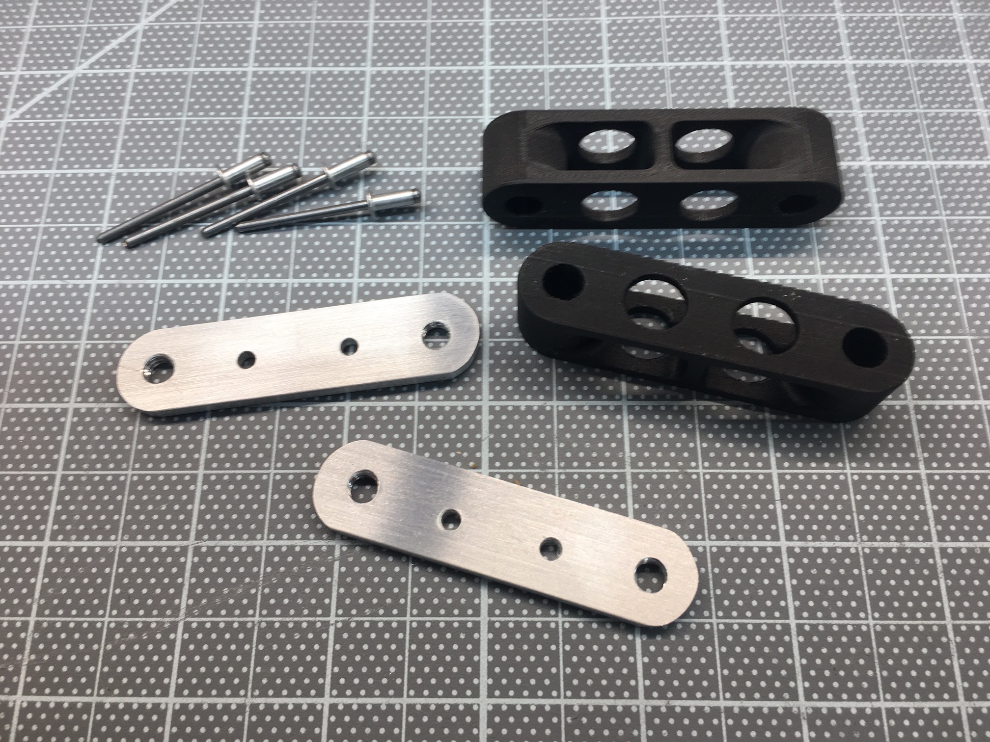
After talking some options through with pnut, we decided that the easiest approach would be to laser cut a reluctor out of steel (a ferrous and therefore magnetic metal) and place it between the brake hat and the hub flange. The Brembo GTs have an aluminum (i.e., not magnetic) hat which shouldn't interfere with the hall effect sensor. Therefore we assume having the relcutor pressed up against it shouldn't be an issue. The hat also has has a flat area which should be wide enough to fit the reluctor's holes and a sensor. The advantage to this approach is that there is no need to machine, drill or tap the hub. In addition, laser cutting holes in a flat piece will be less expensive than machining teeth. 

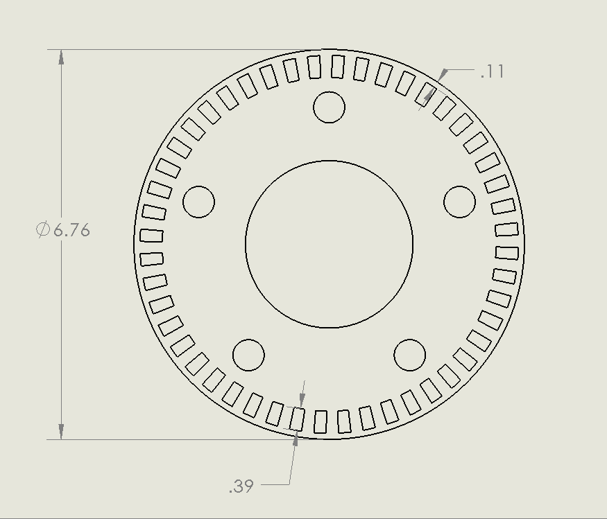
The big question is how thick the reluctor needs to be to have the appropriate magnetic effect on the sensor. In the CAD-generated pictures, I modeled 1/16" which might not be enough. I don't want to go too thick because the reluctor acts like a very thin wheel spacer. I haven't been able to find any information regarding the design of reluctors, so I'm flying a little blind -- OK, no more puns.

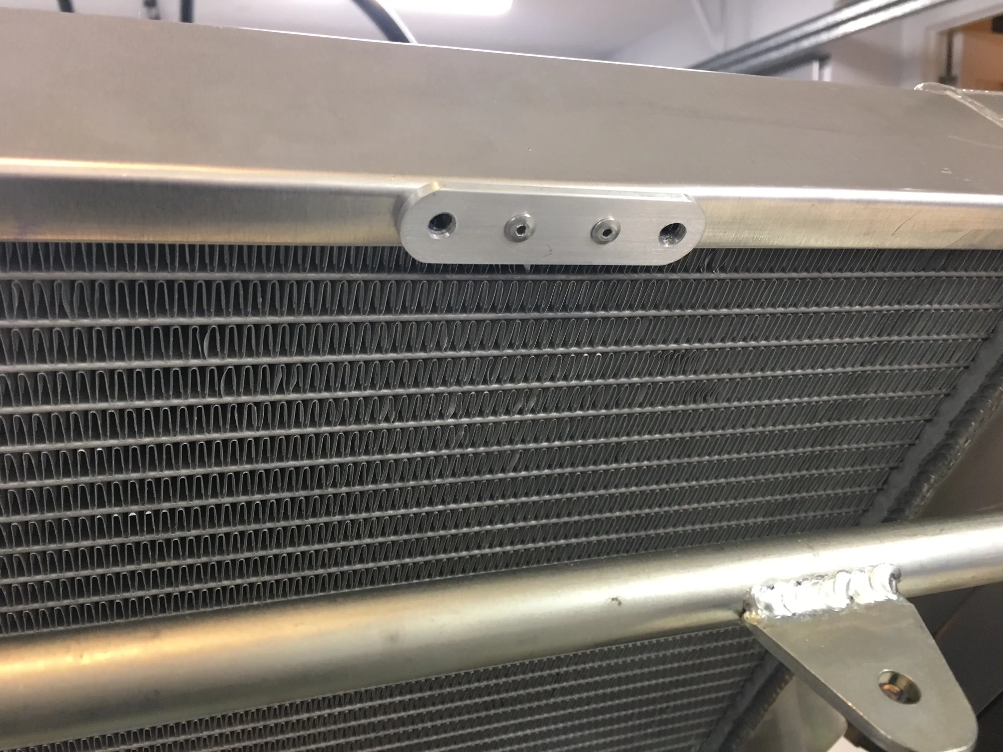
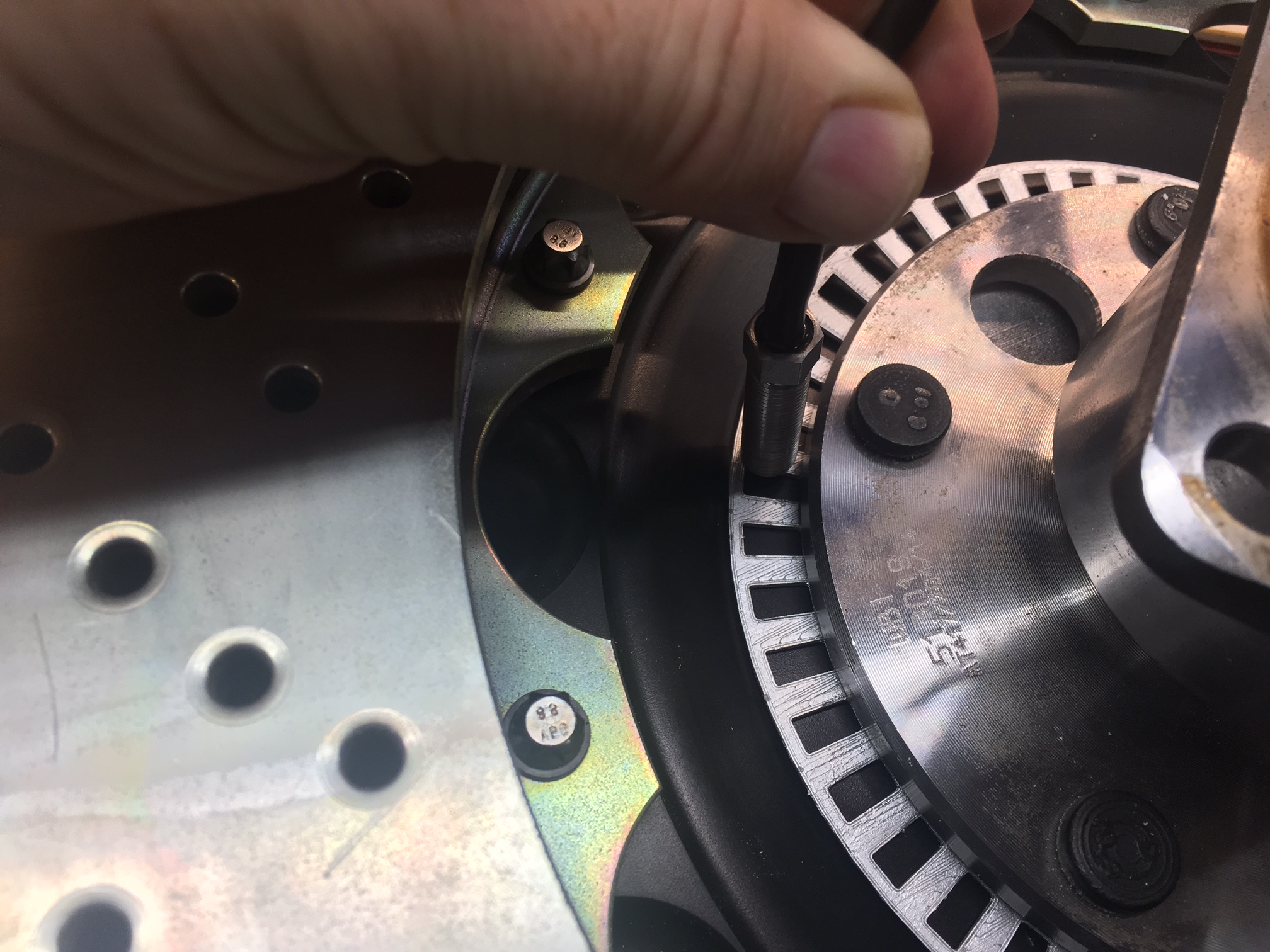
I used SoildWorks to generate all of the images below and I continue to really enjoy using it. Now that I have learned a couple more generic features, I can draw the reluctor in less than five minutes. In the last picture, I 3D printed a prototype and hit it with some silver spray paint so that it would be more visible. As you can see the sensor is close to hub flange. When I took the picture I realized that the sensor was magnetically attracted to the steel hub flange. I'm hoping that this is not an issue because the edge of hub is constant (modulo the wheel studs and holes in the flange).

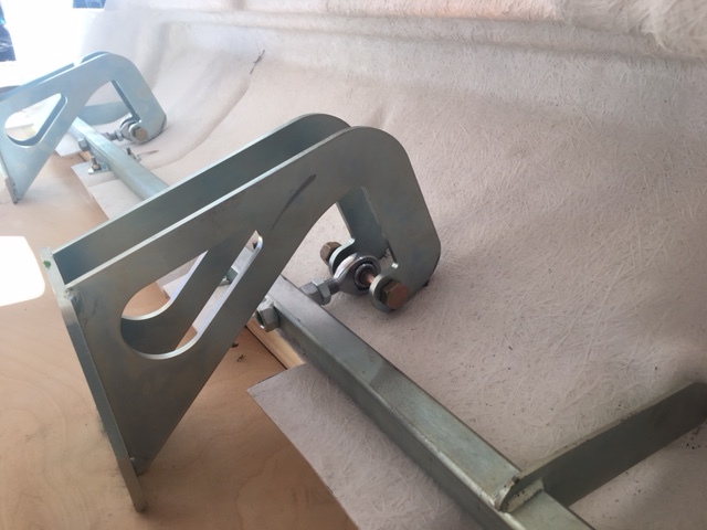
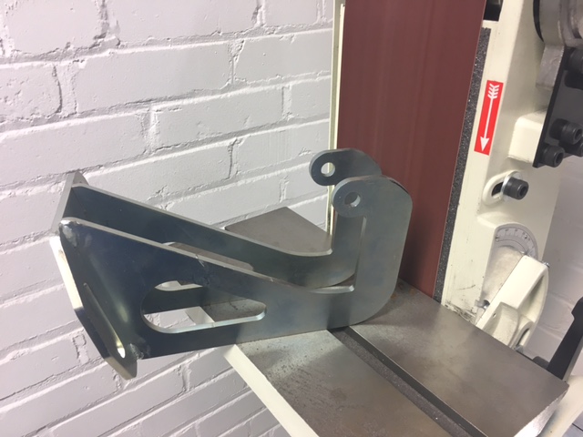
The only way that I know how to test this is to laser cut a reluctor, build a bracket, mount the reluctor and sensor, make a temporary wire harness for the sensor, connect the sensor to power and an oscilloscope, spin the rotor and see if I get nice square waves. Not a big deal, but since I don't have access to cheap laser cutting (one costs about as much as ten), I don't want to go through a lot of iterations on thickness.

Time will tell..

Condenser Spacers and Brackets

I designed and printed spacers and brackets to mount the condenser in front of the radiator. These are printed in medium quality mode in ABS (Acrylonitrile Butadiene Styrene). The final part will be printed in high-quality mode in nylon, but I need to upgrade the extruder and several other parts of my 3D printer to handle the higher temperatures. I still need to carefully tap and drill the top of the radiator because if one of the fins are compromised it will be ruined.

Bottom bracket

I designed the bottom bracket to be made of bent aluminum sheet. I decided to print it so that I could test the fit. McMaster provides 3D download of all of their parts so I able to check the nut's clearance up front. I am surprised at how strong it is. If I decide to go with a nylon print, I'll add some material to the inside bend.

First Fiberglass Mold

Mr. Miyagi would have been proud, FIVE coats of mold release wax!

Mr. Miyagi would have been proud, FIVE coats of mold release wax!

I decided to make a mold and practice part rather than cutting the body any further to experiment with the tail light. If I make a mistake, I can just make another part -- much less crying that way. In addition, this will enable me to sculpt the contour around the tail light on my bench (rather than on the car) and take a mold of that when it's ready... well, that's the theory.

My biggest concern in doing this is that the mold gets stuck to the bodyand wrecks it. This is what I did to make the mold:

  1. Devised way to support tail in vertical position; it's easier to fiberglass with gravity pointing in a helpful direction
  2. Protected the area around the mold with painter's tape and plastic
  3. Applied five coats of mold release wax; wax on wax off
  4. Sprayed 10 coats of Polyvinyl Alcohol Release Agent (PVA)
  5. Applied tooling gelcoat; I couldn't get the !$%@ gelcoat gun to work so I just did it with a brush
  6. Applied 10mil fiberglass surfacing veil and resin; this prevents subsequent layers from showing through the gelcoat
  7. Applied medium-weight cut strand mat and resin
  8. Applied 10oz fiberglass cloth and resin; add bi-directional stability
  9. Applied 2mm high-density bulker mat and resin
  10. Applied 13.5oz chopped strand mat and resin
  11. Fiberglassed mold stiffeners; I used some 1" PVC tube

PVA is cool stuff. It's basically plastic dissolved in alcohol which when sprayed provides a thin plastic layer which keeps the gelcoat/resin from sticking. It's fairly translucent and I was worried that I wasn't getting enough on the surface. So I applied too much and I got a lot of drips and runs. So first try was peeled off. The following day, I applied another ten coats and I went to get a cup of coffee while the final coat was drying. When I went back to check, the PVA layer had a lot of holes in it... PVA is water soluble and apparently there was a rogue drizzle that wrecked it (not noticeable on driveway but there were a couple of visible drops on the garbage can lids). I was on my eighth coat of the third try when the guys redoing my slate roof turned on a leaf blower to clean the 90+ years of dust off before putting down ice and water shield -- really? So let's hope the fourth attempt works.

Did I need that many coats of PVA? Probably not, but I'm paranoid that the mold will get stuck and wreck the body.

I used isophthalic polyester resin because it's allegedly one the toughest resins out there and also offers lower shrinkage and a higher distortion temperature; important characteristics in mold construction. It uses a Methyl Ethyl Ketone Peroxide (MEKP) hardener which is really toxic stuff.

YES MOM, no need to ask again. I am wearing a mask, gloves, etc.

It took a bit of work to get the mold off the tail. Fortunately some YouTube videos let me know what to expect or I would have gotten really stressed out. The PVA worked really well. In the picture to the right, the thin film is the PVA being pulled from the mold. I'm happy with how it came out, but I now realize that I probably made it twice as thick/strong as it needed to be.

I also received my Ricardo transaxle today! They have become extremely difficult to get and I'm very lucky to have a new one. Given my high-HP engine I had it taken apart, inspected, the gears "super polished" and then reassembled and tested on a dyno. I now need to figure out an oil cooler and thermostat.

Bigger isn't Always Better

I needed to drill eight holes (two visible in picture to left) in the chassis for the primary engine mounts. However, the space was too tight for my right angle drill.

Using a cutoff wheel, I was able to shorten a drill bit so that I could drill the hole with more clearance. However the other hole was a no go. What to do?

You have to love internet search and aircraft tools. In the picture below the drill on left is a Dewalt right angle drill with standard length 5/16" drill bit -- well over 3x too large. The air-powered aircraft drill on right has stubby 5/16" drill bit mounted. The bit between the two drills is a 'short' 5/16". To get to that tight form factor, they do away with the drill chuck by using special bits with 1/4-28 threads as can be seen in the close up picture.

Bezel and Tail

Laser-cut plywood bezel outline

I was originally planning massive modifications to the tail to fit the tail lights, but now that the bezels have been fully cut back I realize that they can be made to fit with much less work. To get them to blend properly, I need to extended the bezel. As can been seen in the picture, this results in a lopsided triangle which can be seen on the right side of the bezel. The plan is to try and fit a backup light into this space and if that doesn't work a reflector or a combination of the two. While this simplifies the amount of fiberglass work, it's resulted in a lot of internet searching for lights that can be modified to fit.

The driver-side tail hinge was hitting the body and nearly a quarter inch of its profile needed to be removed. Despite being made of ¼"  steel, the belt sander made short work of it.

I then cut the original tail light box out of the tail... this resulted in a huge hole. The next step is to take a mold of this section so that I can make a copy, cut it up (as opposed to the original), fill in the hole with clay, shape the clay to its final form, take a mold of the new profile, make a part from that, then splice that into the tail. Then repeat it all on the other side... that should be easier because I'll have figured out what to do LOL.