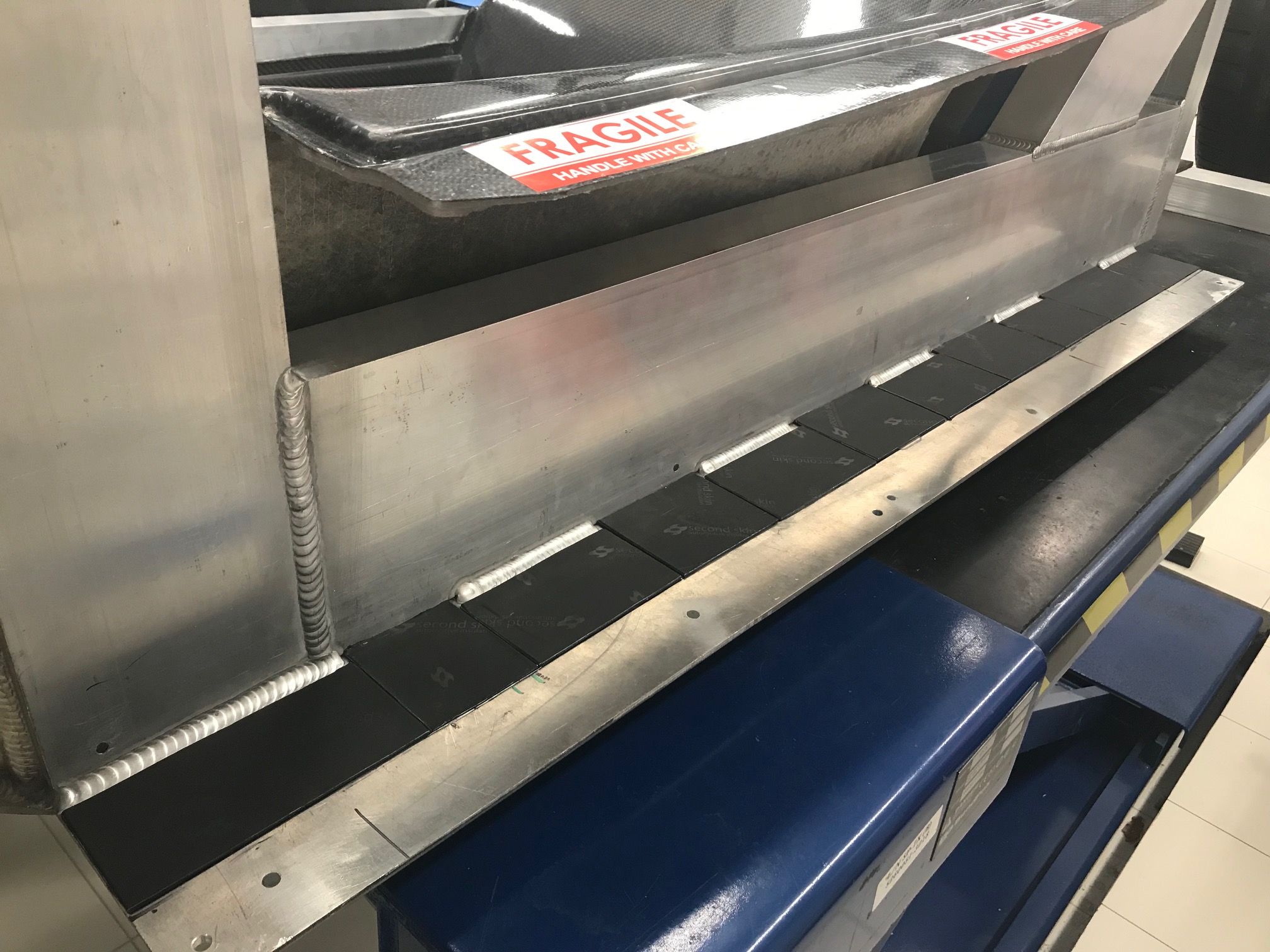
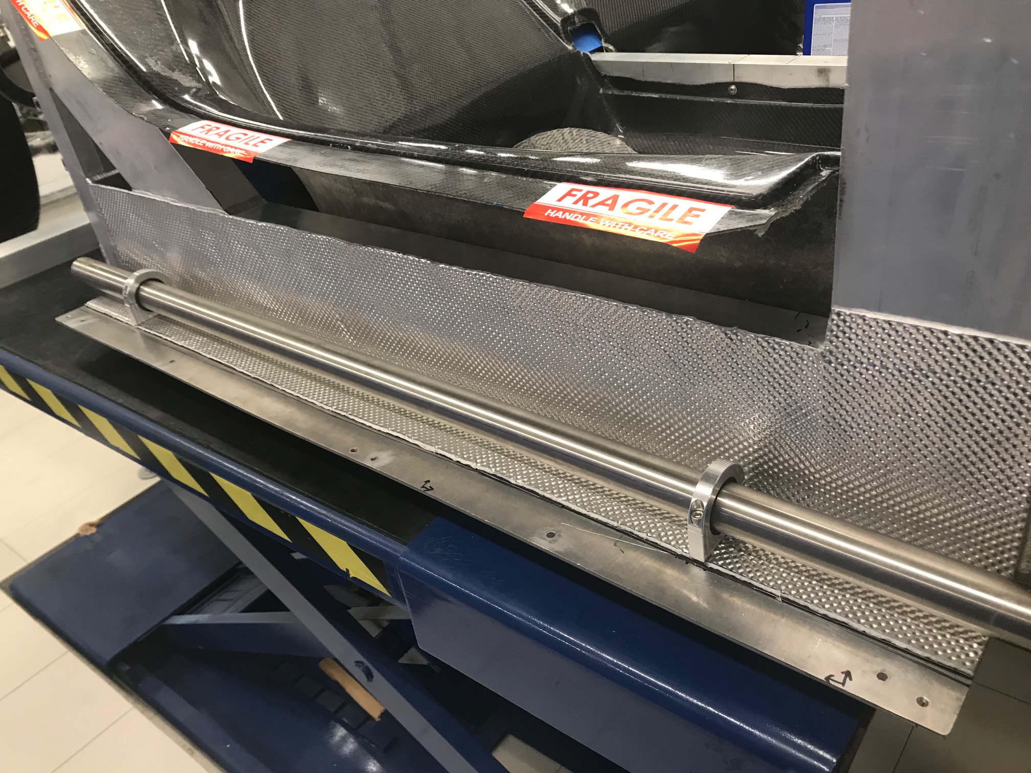
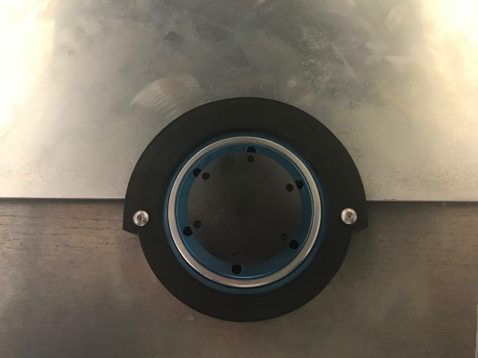
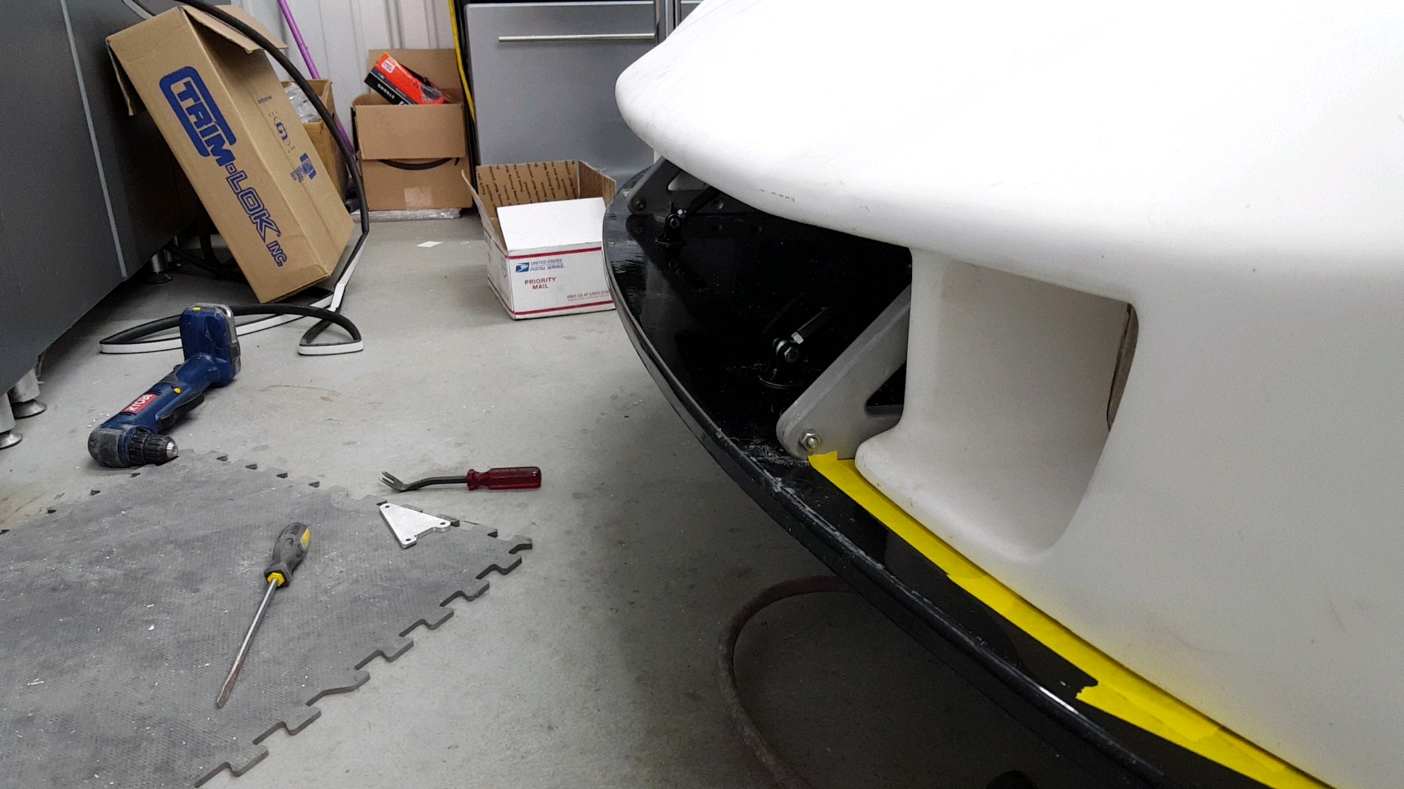
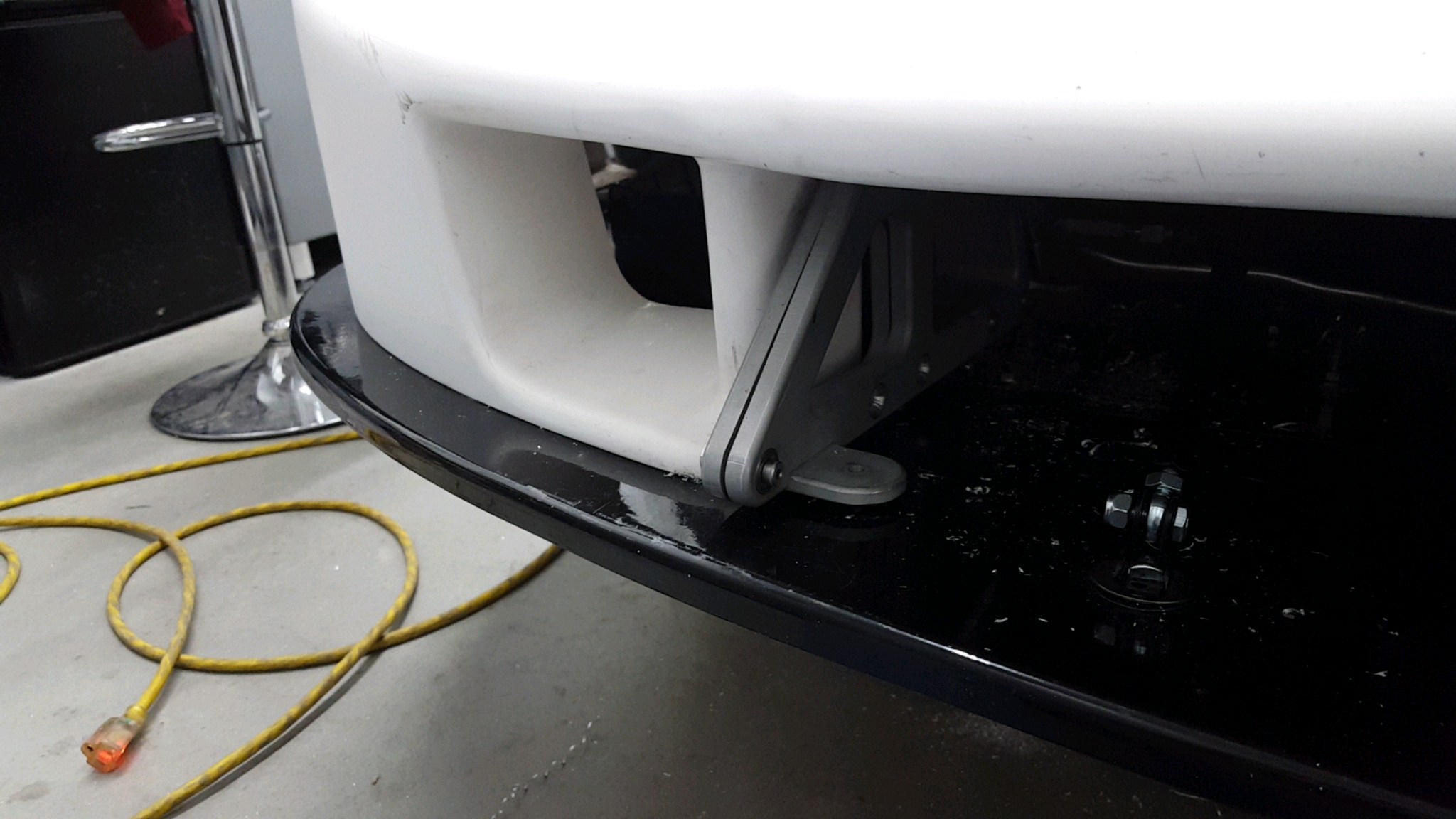
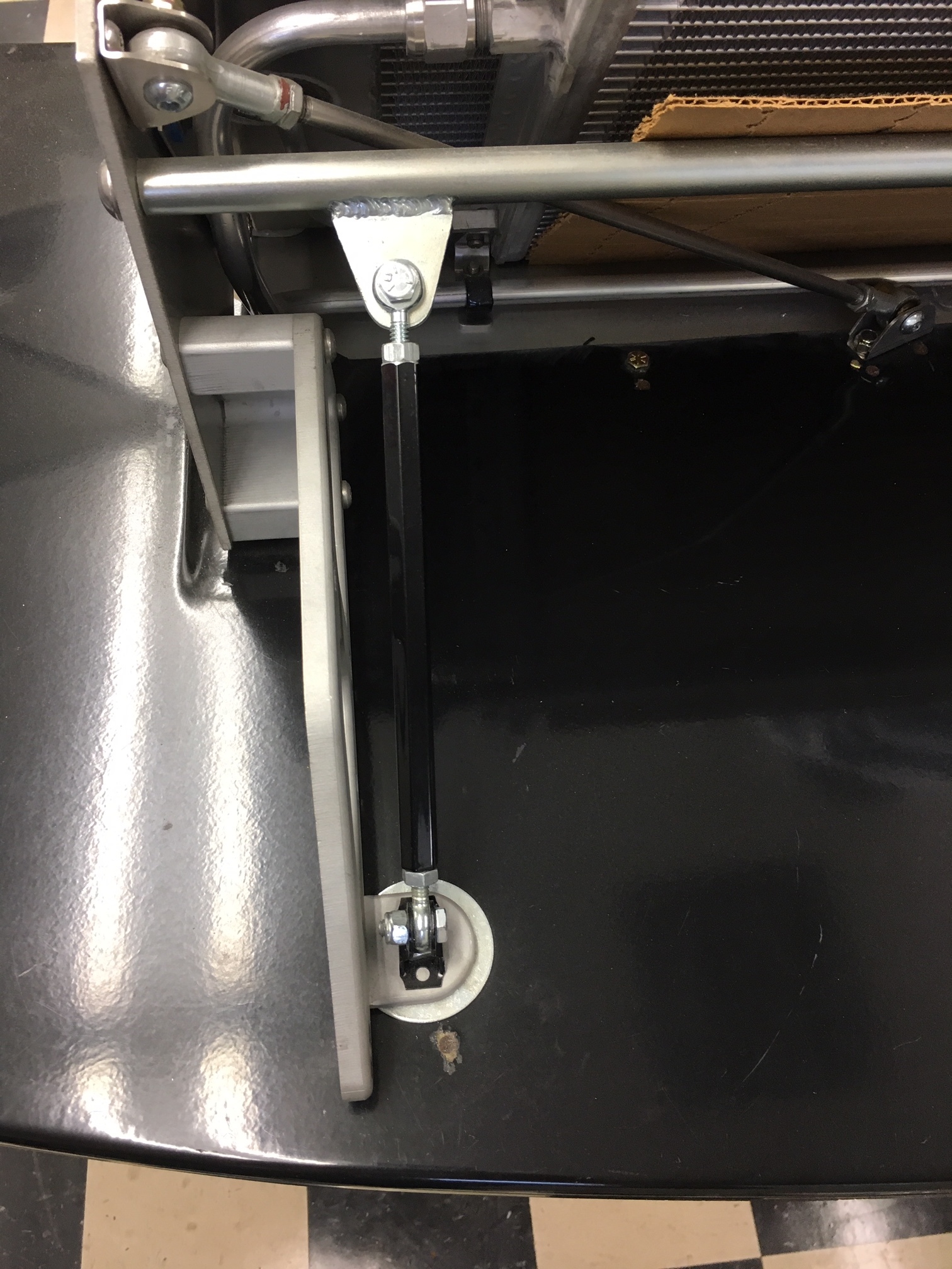
Prototype nose hinge mounted to Bob’s car
The SL-C’s nose is designed to lift off as a single piece. This works great for a race car because there are always crew members around to help you lift it off and you’re not worried about chipping the paint. However, if your crew is composed of your wife and kids, they’re not always available nor happy to be dragged to the garage when watching a movie or sleeping – yeah, last time I woke someone up to help move the nose it didn’t go well. Even with willing familial assistance you have to disconnect the wiring harness, make room to store the nose and you need to be careful not to scratch the paint.
What’s needed is a nose hinge. The primary challenge with designing the hinge is that the splitter, as is appropriate for a performance car, projects in front of the body work. Since the nose pivots forward its leading edge will bind on the splitter unless the pivot point is low and in front of the bottom edge of the nose. There are three general approaches that have successfully been used on SL-Cs, each with pros and cons.
Compound Hinge
A compound hinge raises the nose before allowing it to pivot forward. While there are many nice billet aftermarket versions available, they are generally designed for hoods which are lighter and they likely don’t have optimal geometry. Pros: Least visible when the nose is closed; may have integral gas spring; retains the splitter support rods. Cons: The motion isn’t as smooth as a single pivot point; the nose is wobblier when open; separate pull pins are required to lock the nose in place; and the nose may chafe on the splitter.
Forward Pivot Point
By placing the pivot point in front of the body it clears the splitter. Pros: Smooth motion, retains the splitter support rods; pull pins not required, easiest option to remove the nose (the bolts are outside the body!). Cons: Most visible (it protrudes in front of the nose); nose may chafe on the splitter; most difficult to implement (with a kit, it’s the easiest) .
Recessed Pivot Point with Rotating Splitter
The nose is attached to the diffuser and the pivot point is placed inside of the body. Pros: Smooth motion, splitter is strengthened, nose won’t chafe on splitter. Cons: All splitter and nose forces are supported by two pivot points mounted in fiberglass, the splitter support rods are removed (Fran doesn’t recommenced doing this for car that will see high speeds), heat exchangers can’t be mounted to the diffuser, more difficult to implement brake duct hoses.
Approach
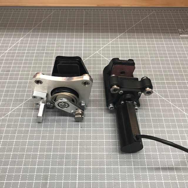
I decided to go with the Forward Pivot Point approach because it offers smooth motion and allows me to mount the supercharger’s heat exchangers on the splitter. While noodling on the on the problem I discovered that Bob, another SL-C builder, had built a working prototype. The following video demonstrates how easy the nose is to open when gas struts are installed.
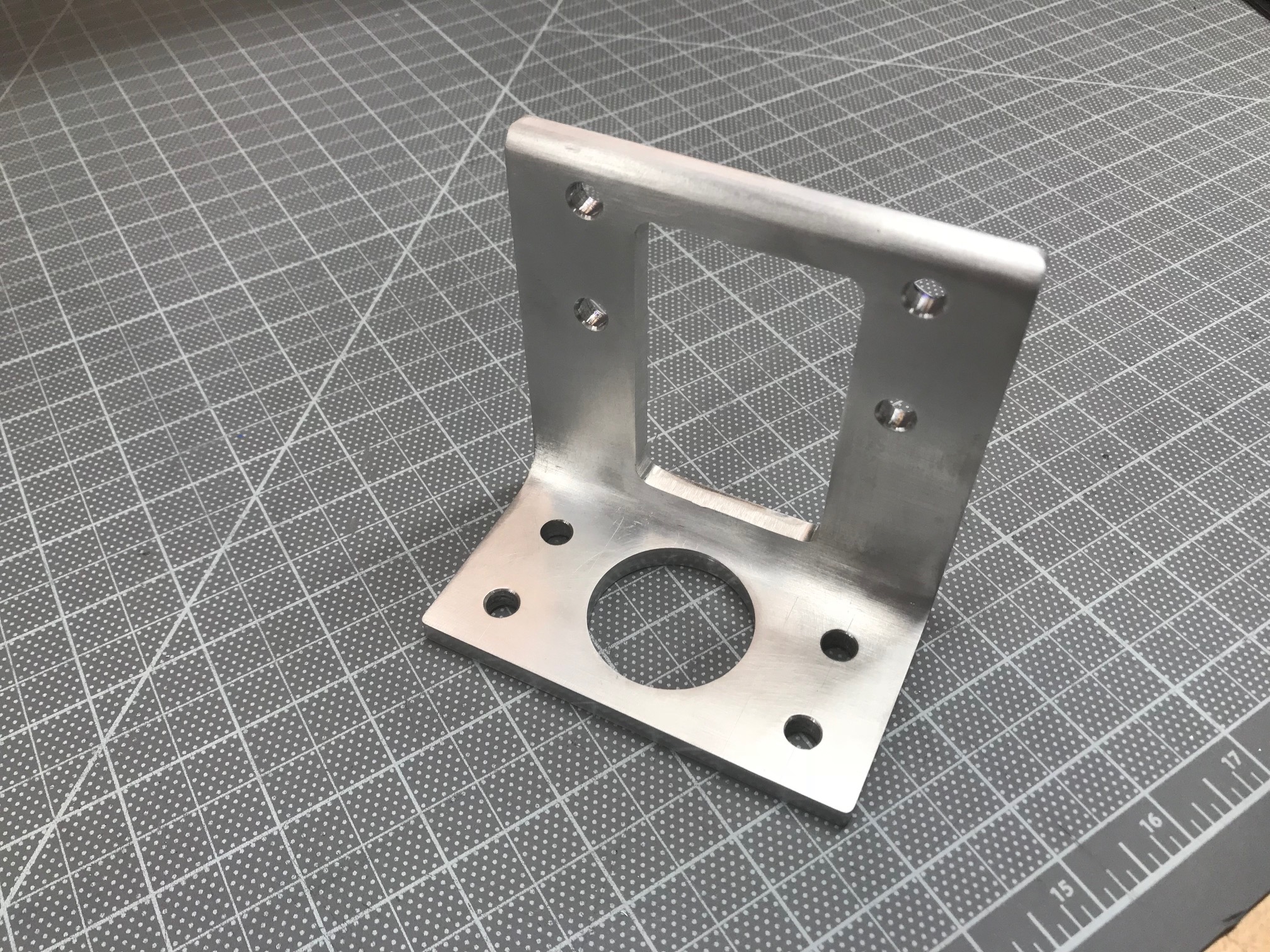
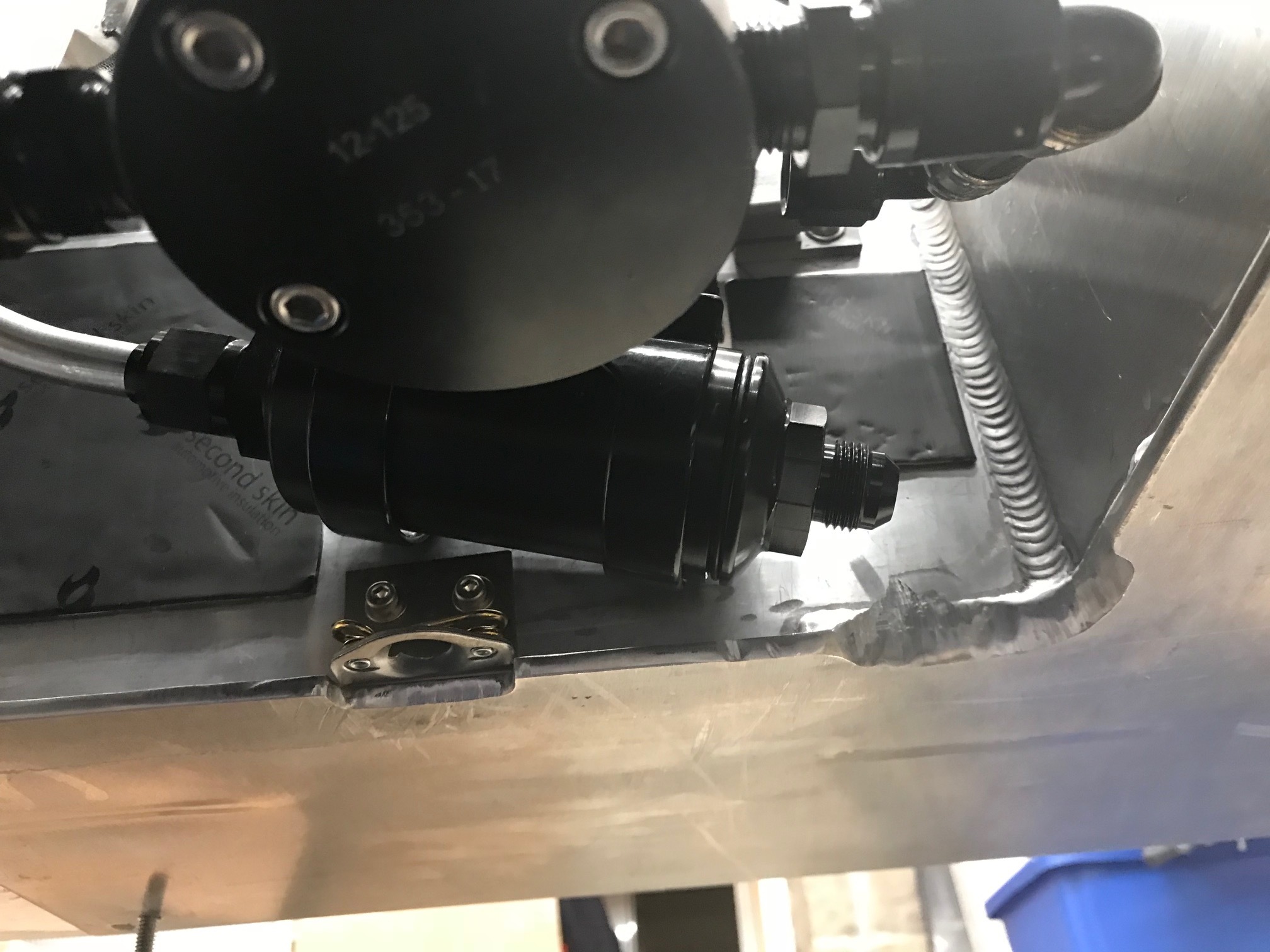
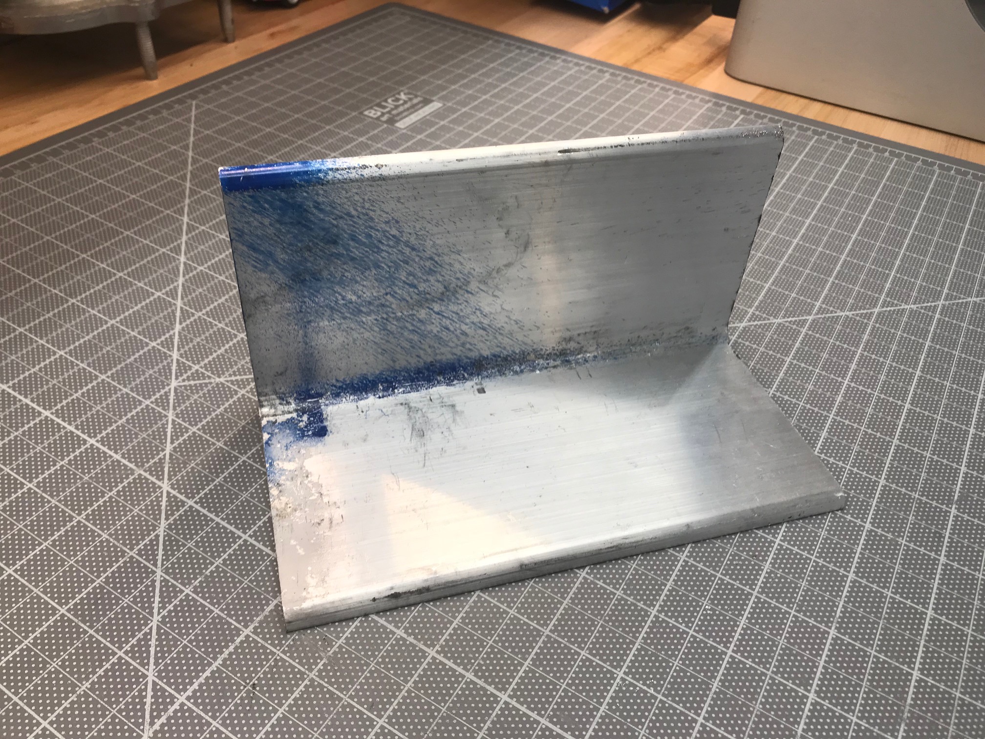
Bob shipped the prototypes to me and I tweaked and redrew them in SolidWorks. I then sent them to Allan and he installed them on a SL-C that he’s building (see picutres below). Based on Allan’s feedback, I relocated a few of the mounting holes.


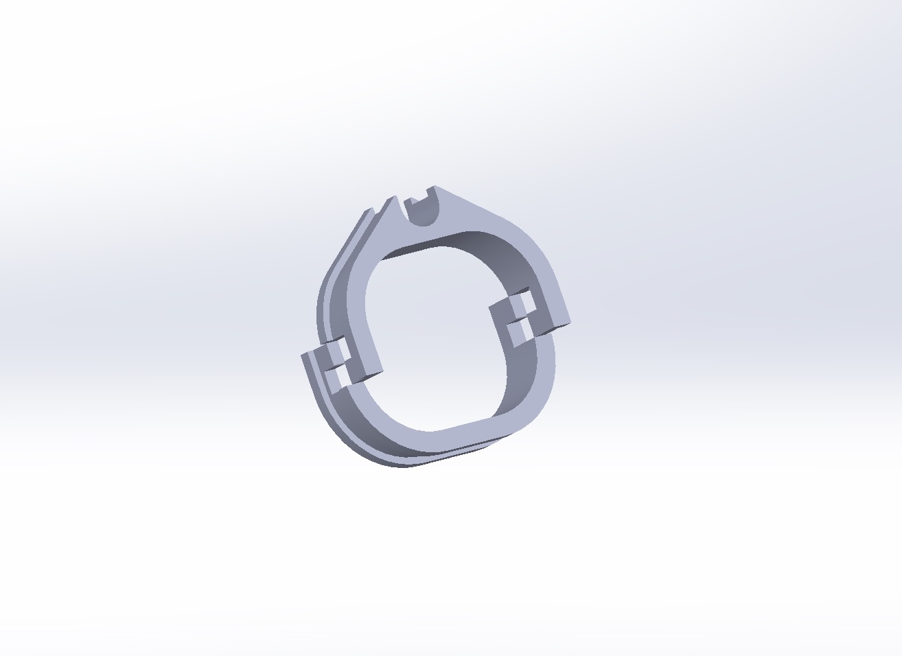
The following video shows the updated CAD model. The plan is to do a group buy. The two largest pieces have left/right mirrors, so they take twice as long to achieve volume pricing as the other pieces. The target is to have a minimum order of at least ten hinge sets. Here are the top-level features:
Billet 6061 aluminum
Arms are 3/8” thick
All hardware, other than gas struts, is supplied
Stainless Steel mounting hardware from McMaster
Steel ball bearings from McMaster
Steel drilling jig
Depending on the shipping costs, we may or may not provide the gas springs.
We’re currently looking for someone to machine it!