Yep, that's a lot of island top to not see greasy finger prints
The Eyeball Saga
It's been a while since my last post. I had a vein burst under my cornea which resulted in a huge dark gray hole in my vision with warped vision around the hole. Apparently the gray hole is caused by blood and the warped vision is caused because the cornea is bulged (i.e., the optics are bent). Using only my left eye, I could see the upper-right-hand corner of the eye chart. I don't mean blurred letters, but rather about an inch of one of the corners that indicated where the chart was supposed to be. It's certainly made working on tail light shaping impossible.
On the positive side, I now have selective vision in addition to selective hearing -- no, sweetie, I really don't see those greasy finger prints on the kitchen island LOL. While there is no cure, the treatment is getting three shots into the eyeball, one month apart... and I want to pass out when they take blood!!! Good news is that my vision is much better. Bad news is that I go back for the second shot tomorrow.
The Reluctant Reluctor


One of the things that I've been working on is the traction/launch control system. One of the challenges with the SL-C is that there isn't a good way to connect speed sensors to the front wheel hubs. Apparently the hubs have an integral reluctor, but to utilize them I'd need to machine the uprights which would compromise their integrity.
I'm using a Hall Effect Sensor and for it to work properly it needs to be 0.030" to 0.060" from a spinning ring (commonly called a reluctor ring or a tone ring) which has evenly-spaced magnetic and non-magnetic areas. This will create a square wave whose frequency is proportional to the wheel's speed.
After talking some options through with pnut, we decided that the easiest approach would be to laser cut a reluctor out of steel (a ferrous and therefore magnetic metal) and place it between the brake hat and the hub flange. The Brembo GTs have an aluminum (i.e., not magnetic) hat which shouldn't interfere with the hall effect sensor. Therefore we assume having the relcutor pressed up against it shouldn't be an issue. The hat also has has a flat area which should be wide enough to fit the reluctor's holes and a sensor. The advantage to this approach is that there is no need to machine, drill or tap the hub. In addition, laser cutting holes in a flat piece will be less expensive than machining teeth.
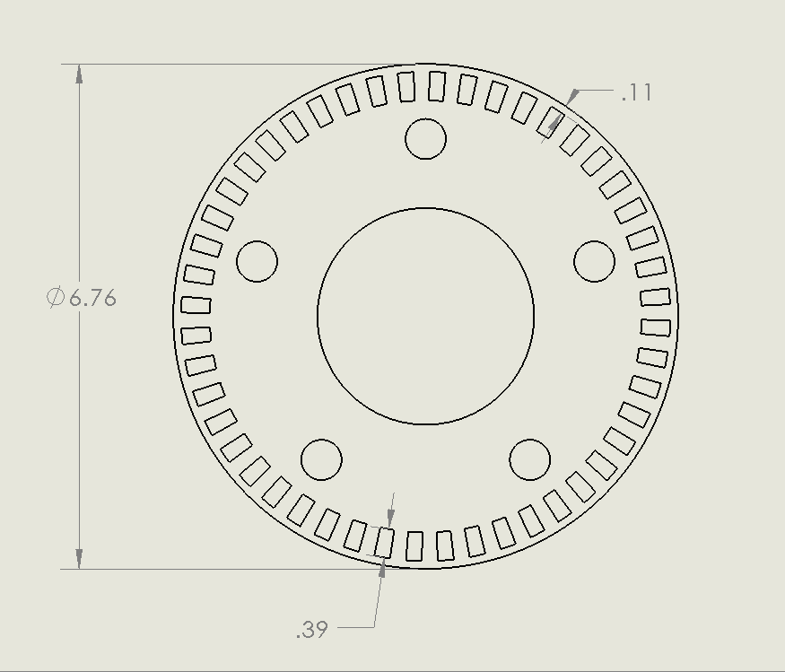
The big question is how thick the reluctor needs to be to have the appropriate magnetic effect on the sensor. In the CAD-generated pictures, I modeled 1/16" which might not be enough. I don't want to go too thick because the reluctor acts like a very thin wheel spacer. I haven't been able to find any information regarding the design of reluctors, so I'm flying a little blind -- OK, no more puns.
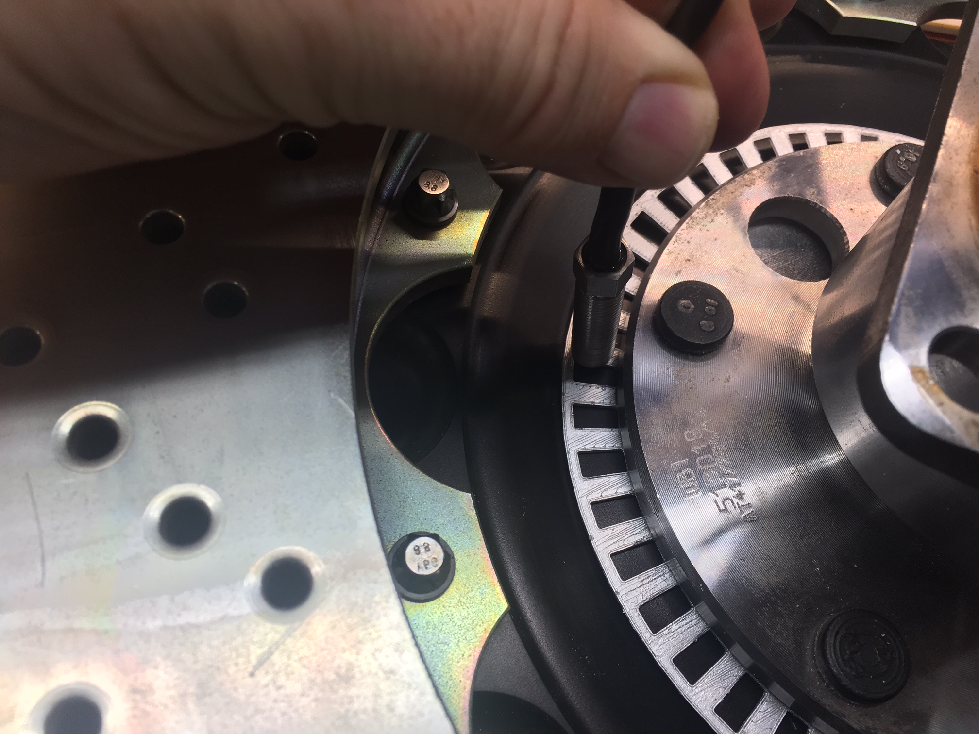
I used SoildWorks to generate all of the images below and I continue to really enjoy using it. Now that I have learned a couple more generic features, I can draw the reluctor in less than five minutes. In the last picture, I 3D printed a prototype and hit it with some silver spray paint so that it would be more visible. As you can see the sensor is close to hub flange. When I took the picture I realized that the sensor was magnetically attracted to the steel hub flange. I'm hoping that this is not an issue because the edge of hub is constant (modulo the wheel studs and holes in the flange).
The only way that I know how to test this is to laser cut a reluctor, build a bracket, mount the reluctor and sensor, make a temporary wire harness for the sensor, connect the sensor to power and an oscilloscope, spin the rotor and see if I get nice square waves. Not a big deal, but since I don't have access to cheap laser cutting (one costs about as much as ten), I don't want to go through a lot of iterations on thickness.
Time will tell..