My -10 is Bigger than Your -12

I've been trying to figure out the engine oil system and I've been looking at thermostats to be used in conjunction with a oil cooler. I had been looking at Improved Racing's FSM-165 which has a patent pending, hi-flow, low pressure drop design. I was about to click on the buy button when I realized that while it can be ordered with -12 AN male fittings, the female ports are just -10 AN.

@&#%! This is a problem because the manufacturer of the oil dry sump, Daily Engineering, is very specific that the pressure line (i.e., connection between the pump and the thermostat) must be -12. So, I spent a lot of time looking for a thermostat with -12 capacity all of the way through and only found one which I didn't like nearly as much as Improved Racing's. 

I contacted Improved Racing and they had good news. The ID of a standard -12 AN straight hose end is 0.58" and their male fittings have an internal ID or 0.60". In addition, Improved Racing's thermostat is much less restrictive than other brands. The pictures below compare their thermostat to Mocal's, note how open their's is. In any event, the point is that even though the FSM-165 has -10 female ports it will be the least restrictive part of the -12 pressure line.

Pillow Block = Sleep Block

It took over six months to get the cockpit adjustable sway bars. They are a combination of parts from Genesis Technologies as well as custom fabricated parts. The supplied pillow blocks which mount the sway bars to the chassis are beautifully machined and polished. However, they are supposed to allow the sway bar to rotate and they pinch it. In the picture to the left note that the screw holes were machined too close to the inner diameter and that the screw threads are exposed. It was suggested that I try to open them up with some 180-grit sandpaper, but that only created a flat spot on the offending thread. I'm not sure what the machinist was thinking... these are headed into the bin.

I started down the path of designing new ones when I stumbled into HRP World who manufacturers and resells Genesis Technologies parts. They offer pillow blocks for a variety of sway bar diameters, but they didn't have any with a 1⅜" ID. So I contacted them and a couple of weeks later they sent me four custom ones, two for the front and two for the rear. As you can see in the picture below, they are a lot more robust than the supplied ones. However, vertical space is tight and after contacting HRP World, I had 0.125" machined off of the top and bottom (left and right in the picture) at a local shop. In the picture below; the front one is the supplied one, the back left is as received from HRP World, and the one on the right has been machined and then hit with a metal finishing pad. The next step is to install them on the front of the monocoque.

T-Rex Arms

Sucks to have T-Rex Arms

When I removed the center body section it took a little while to undo the five screws/nylocs on each side that attaches it to the chassis. The reason for this is that the bolts are mounted from the bottom of the car and you need to get a wrench on the nuts in the interior to keep them from spinning. I don't have long arms (no, they aren't T-Rex arms) and I needed another person to remove several of the screws.

In any event, I'm in the process of filling up the side pods with cooling, heating and A/C lines which will make installing and removing these screws much more difficult in the future. I considered using a long piece of aluminum and tapping five holes into it. The primary issue with that approach is that each side would need a piece nearly four feet long which costs money and adds weight. Worst yet, there wouldn't be anything to prevent the screws from shaking lose.

To solve this problem I decided to take a page from aircraft construction and use self-locking, floating nut plates. A nut plate provides a way to add a captive nut behind a panel. In other words, you don't need to prevent the nut from spinning because the nut is riveted to the backside of the panel. In addition, the self-locking type have an asymmetrical thread which deforms and locks the screw into place. Unlike jet nuts, these nuts can be reused several times, but should be replaced when there isn't resistance when tightening. The floating version enables the nut to move forward/backwards and left/right allowing some misalignment during assembly which is very useful when mounting the body to the chassis.

Mounting plates cut from the fan cutout scrap

Since the nut plate needs to be fastened on the fiberglass side I was concerned with how close the rivet holes were to the fastener's hole. To resolve this, I designed a mounting plate and had a bunch water jetted out of 1/16" aluminum. This was essentially "free" because I cut them at the same time as fan shroud and they fit within what would have otherwise been scrap. I wanted the plate to sit flat on the fiberglass, so I used NAS1097AD3 rivets. They are 3/32" solid rivets that allow flush installation even in thin materials. The reduced head makes them inappropriate for use in a structural shear application, but I'm just using them to keep the nut plates from spinning.

In the picture below:

  • Solid rivet manual squeezer
  • 100-degree counter sink
  • Mounting plate with the inner two rivet holes countersunk (doesn't take much)
  • Two 3/32" solid rivets (NAS1097AD3); note how small the heads are
  • 6-32 floating, self-locking nut plate
  • Rivets held in place with painter's tape (made riveting much easier)
  • Bottom of mounting plate post riveting (note that the rivets are perfectly flush)
  • Nut plate riveted to mounting plate

I haven't figured out what types of rivets to use to attach the mounting plates to the fiberglass, but it will be a long time before I need to sort that out.

No Bullshit Fuel Filter

You gotta love a company like Injector Dynamics who puts the following on their home page and then walks-the-walk by offering innovative products backed by data:

As a results based engineering company, we have a STRICT no BS policy. Our product information is backed by data, and sound engineering principles. Our strict adherence to facts has earned the respect of many, but our willingness to call BS when we see it has created a great deal of controversy. We accept this controversy as a small price to pay for holding the industry to a higher standard, and we will continue to push for a motorsport community that makes decisions based on facts, not buzzwords, nonsense, or outright falsehoods.

I saw this video made by the company's founder over a year ago and have been hounding them since. They don't have it on their site for sale yet, but I just got mine in the mail today...

Note that "April" was for 2016... they didn't want to release it until they had it right which is fine by me.

It came very well packed in a large box packed with the starch-based peanuts so they score well with environmentalists as well as my kids who love to dissolve them in the sink. I'll only outline what's in the video and this spec sheet:

  • Only filter I've see with actual testing data;
  • Meets Bosch's specification for the protection of fuel injectors
  • Holds a high-level of contaminants while maintaing low restriction to flow
  • Delta pressure gauge indicates how clogged the the element is
  • Schrader valve to relieve pressure and drain gas
  • Spin on/off canister with no-tool safety latch
  • Optional pressure and temp block and sensor
  • Integrated mounting bracket

Heater Control Valve (HCV)

I started working on the heating and the cooling system. The first step was to make a diagram to ensure that I understood how everything was connected.

I keep stumbling into little things that are different with a mid-engine car and I found another one. In a front engine car, the engine (the heating source) and the heater core are very close to each other. In a mid-engine car, the cockpit is between the two. Since it's important to keep the cockpit cool, the last thing I want to do is pump hot water from the engine, through the passenger side of the car, into the heater core under the dash and then have if flow back unused. To prevent this from happening an electric heater control valve (HCV) is installed in the tail section. However, it has been reported that the LS engine can overheat if you start your engine with the A/C on and you have a heater control valve that simply closes the water pump's heater outlet. In other words, LS engines need a constant loop of coolant flowing through the water pump's heater outlet.

To solve this issue, several other builders have used this heater control valve made by Old Air Products which allows coolant to flow even when the heater is turned off. The business end has four 5/8" hose barbs and a valve. Connected to the valve is a servo which is wired to a separate servo controller which is in turn wired to a potentiometer. This provides continuous adjustment from closed to fully open. There are five wires (two for power and three for the position feedback potentiometer) so it's a closed loop control system.

A quick search on the name on the actuator turned this Voltage Control Actuator from Newbase, a Chinese company. The only moderately useful information on that site is the pin out and that it draws a whopping max 300 mA. There is a dimensioned drawing of the locations of the screws that attach the actuator to the valve. Well, the drawings are wrong... I get that it's hard to translate from Chinese to English, but the dimensions were in millimeters!

I considered controlling the HCV via MoTeC by replacing the potentiometer with a digital potentiometer controlled by an Arduino which would then be interfaced to the MoTeC. It would work, but it's a fair amount of work, introduces a bunch of things that might break and I don't really gain anything... nah, not worth doing.

The HCV is awkwardly shaped and there is no easy way to mount it. While pondering the best way to mount it I noticed that the actuator fit perfectly in a triangular dead space in the 2" x 6" chassis. I then realized that I could remove the three screws and and spacers connecting the actuator to the valve and sandwich an aluminum bracket and replace the spacers with shorter ones... OR I could just print a panel large enough to seal the hole (something that was on my to do list) and mount both the motor controller and wire connector. 

The panel is sandwiched between the valve and actuator, thus replacing the standoffs. It was made large enough to cover the hole and mount the motor controller and a new wire connector. There wasn't a way to mount the motor controller so I simply drilled the cover plate mounting holes all of the way through and used stainless 4-40 screws and nylocs. Since heat rises, I decided to print a heat shield between the heater lines and the motor controller and to put Reflect-a-GOLD (aka TRUMP TAPE) on it. I cut 80% of the harness off and terminated one end into a Deutsch connector. I removed the connector to the actuator, fed the wire through a vinyl grommet and re-terminated it on the back side. Since I couldn't figure out what type crimp connectors were used I carefully cut the old ones out of the harness and soldered them on. Everything now fits on one tidy panel!

TRUMP Tape

I ordered a roll of Reflect-A-GOLD tape today. It's a metalized polyimide laminated to glass cloth which is good at reflecting radiant heat. When I first saw I thought it was over the top, but it's recently started to grow on me. I'm now thinking about using it on the tube frame in the engine compartment like the car in the picture below.

That got me to wondering if the over exposure to Trump has had an effect on my senses. Reflect-A-GOLD has a lot in common with Trump:

  • An affinity for flashy gold
  • Ability to reflect heat
  • Tacky
  • Thin in terms of substance

Apparently it's easy to install. but time consuming and difficult to get a clean, wrinkle free result like the car above. I'm a perfectionist and I'm a little concerned that that after a bunch of hair pulling I might wind up with a Trump hairdo in addition to a Trump-like engine compartment!

Lars Anderson Auto Museum

My son doesn't have school this week and we decided to drop by the Lars Anderson Auto Museum. It's about a half mile from our house and it houses "America's oldest car collection." He hadn't seen the new Porsche and BMW display which features a Porsche speedsters, 959s, 930 turbo and a 956, plus a BMW M1. The 956 was my son's favorite car.

The Anderson's Stable

If you're in Boston, it's worth a visit. It was built in 1888 as a stable, but began to house horseless carriages starting with the purchase of an 1899 Winton Runabout. When Isabel Anderson passed away in 1948 she bequeathed her entire Brookline estate, including the mansion, Carriage House and land to the Town of Brookline. Fourteen of their cars remain, including two electric cars built in the 1920s.

I got the picture with grass off of the web, still snow on the ground in Boston! That's the stable, the mansion burned to the ground years ago.


Unit Test Reality Check

Well, the "unit tests" that I wrote about in the last post only take you so far. When I went to mount the parts I realized that I hadn't made recesses to accommodate the rivnuts that I had inserted into the radiator. Rivnuts (aka rivet nuts) are really useful and if you don't know what one is, this video does a pretty good job explaining it.

In the picture below, you can see that have been installed in the radiator (silver) and that they have a lip that protrudes. A simple thing to fix, but it required me to print the parts again. There is an unused rivnut sitting on top of the condenser (black). Rather than using wimpy aluminum rivnuts I opted for zinc-plated steel ones. In addition they're ribbed for the the condenser's pleasure... ahhh, I mean to help prevent it from spinning in the hole.

The unit tests aren't a guarantee, but they a did allow me to quickly refine the design. In any event, I'm really pleased with how the brackets came out.

Cycle Time, Unit and Functional Testing

Unit and functional testing is critical to software development, but it also extremely useful when printing 3D parts. It can significantly reduce the cycle time and material to develop a part. More importantly, it can result in a high-quality, well designed part.


In computer programming, unit testing is a software testing method by which individual units of source code... are tested to determine whether they are fit for use. Intuitively, one can view a unit as the smallest testable part of an application.
— Wikipedia

When creating "unit tests" for a 3D-printed part, you want to print the smallest piece possible to validate the critical dimensions that you're worried about. For example, I recently designed a bracket (see pictures below) that mounts the bottom of the condenser to the bottom of the radiator. While not a complex part, there were several critical dimensions that I knew would take me a couple of iterations to get right. Rather than printing a full size prototype, I broke it down into "unit tests." Once the part is designed, you can usually use one or two extruded cuts to slice the completed part into something that you can use to unit test. SolidWorks allows you to suppress these cuts and save them in part file... yeah, just like software you sometimes make a change that breaks something else and the more complicated the part, the more likely it is to happen!

The picture below shows the four steps to get to the final production parts. From left to right:

  1. The profile of the part was printed on paper in 1:1 scale, cut out and trial fit. I needed to extend the part that touches the radiator by 0.05" and I noticed that I had room for a internal fillet.
  2. I made the changes and then printed a 0.025" slice in Onyx. Oops, that 0.05" should have been more like 0.04".
  3. After making that change I printed a section to test: (1) the part that fits into the bottom of the radiator and (2) the hole that is recessed into the sloped face. Typically I would have split this into two tests, but I already had designed a bracket for the top of the radiator so I was pretty sure I would get the right. Number one was perfect and when snapped into place it was held there by friction (I think that took me two or three times to get right when doing the top bracket). Number 2 wasn't so successful. I was able to get a washer to sit flush in the recess after using a utility to carve the sides a bit so I increased the diametera bit.
  4. Final print.
IMaterialPrint Time (Minutes)
1 1 Sheet Paper  0.1
2 0.21 cm³ Onyx  5.0
3 4.14 cm³ Onyx 34.0 
4 25.02 cm³ Onyx 153.0

The value of the unit tests becomes apparent when you look at the amount of material and time for each iteration. The savings become even more dramatic for a larger or more complex part. I got to an optimal part (at least in my mind LOL) in a small number of iterations. Having a 3D printer in the garage made that a fast and easy process. If I had to send the part out to be printed the elapsed time would have been much longer and the part not as good. Less iterations means less chances to tune the part and you're likely to say "good enough" much sooner than you would with a short cycle time. My recommendation is that if you're going to design a bunch of 3D parts to at least get an inexpensive printer so that you can quickly iterate designs and then have the final part printed by someone else with a high-end printer.

SettingUnit TestDefault
Fill Density (%) 1 50
Wall Layers 1 2
Roof & Floor Layers 1
Layer Height (mm) 0.2 0.1 

The unit tests were printed with the settings to to reduce time and material. The table below shows the settings that I used for the unit test vs. the system defaults:

The unit test parts can also be useful for destructive testing. If it's strong enough when printed at unit test settings, then it's going to be more than strong enough in the final print. In addition the final part was ~2.5x wider and has an additional screw, which provides a lot of margin.

Well that didn't work for this part. It was pretty easy to break the one-inch wide, crappy print. After going to install the final part I decided that the part overhung the bottom of the radiator by 0.06". It doesn't affect anything except my OCD. So I decided to destruction test that one. I had to get a bigger set of pliers to break it and it broke where you'd expect it to break. It's strong enough as is and don't I think that I'm going to use any continuous strands in the final-final print. That said, given the print orientation the continuous strands would be optimally oriented and I could make that axis as strong as a solid aluminum piece.

...yeah, like software you can keep just tweaking it...

No Lonely Tools

I attempted to take apart the stub axle and rear hub the other day. I found that I needed to buy several more tools: a 10 mm long hex bit socket, a 36 mm deep socket, a 30 mm socket and a puller. Since I have a strict policy of no lonely each was bought in a larger set.

I probably could have tapped the rear hub off with a rubber mallet, but I didn't want to risk damaging the bearings. As can be seen in the pictures above, the puller has a pointed shaft which is placed in the dimple at the end of the axle. The three arms are then hooked under the hub's lip. This puller is nice because each arm has multiple ratchet positions which keeps the arms from flopping all over the place when you're trying to set it up. As you tighten the nut even pressure pulls the hub off of the shaft.

To Shroud or Not to Shroud?

Cooling is a challenge for a high-HP, mid-engine car. This is exacerbated by the SL-C's extremely low, front-end profile which makes the car very aerodynamic, but doesn't leave a lot of room for a radiator. In fact, the radiator is sloped 55 degrees just to achieve a core area (i.e., the fins that act as a heat exchanger) of 24" x 11.5".

When driving, air flows through the entire core. However, when stopped air only flows through the area directly in front of the fans. Generally speaking this is a bad idea for any car that is ever going to idle or sit in traffic. To get around this issue, most OEM cars utilize a fan shroud which, when properly implemented, results in air being forced through the entire core. The downside is that at speeds at 20-30 MPH the shroud restricts air flow and can cause overheating while driving. This can be solved by adding one or more flaps which are forced closed by the vacuum created by the fans pulling air across the shroud (assuming the shroud is properly sealed) and forced open by wind pressure as the car picks up speed.

The kit ships with a really nice custom-made aluminum radiator, two decent fans (I believe 1,200 CFM each) and no shroud. SL-C builders disagree whether or not a shroud should be used. I spoke with Chuck at Superior Radiator who manufactures the radiator and he suggested a shroud and upgraded fans, all of which I bought from him. The shroud is made of 0.65" aluminum and the fans are much larger than the ones that came with the kit (in the two pictures below, the new fan is on the left).

The old fans are rated at 1,300 CFM whereas the new ones are rated at 2,000 CFM. Chuck indicated that they are more of a wholesale item with a minimum purchase of 100 units so I don't have a part number.

He didn't think that I'd need flaps, but I decided to add two just to be safe. I wasn't sure what to make them out of so I ordered two from Summit Racing. They were replacement parts and as such had no specifications. The SPAL Automotive ($1.31) and Be Cool ($6.99) flaps were indecipherable. Fortunately, at 3.3" x 2" they were a perfect fit. There is nothing special about them. They're made out of floppy 0.4" rubber and have three molded mounting spikes which I cut off. So, it's trivial to make your own.

Here are the high-level modifications I made. The fans were a little too close together and the lip of the right one was sitting on top of the lip of the left one which result in a poor seal between the fan and the shroud. To remove the fans I drilled the rivets holding them in place...

I will have temperature sensors on both the cooling and AC pipes and I'm in the process of figuring out how to control the fans with the MoTeC ECU and Power Distribution Modules (PDMs). Each fan draws 17 amps when running and 23 amps when starting up. This gives me two options:

  1. Use a single 8-amp output to drive an external relay
  2. Use a 20-amp output for each fan

MoTeC: Coolant Temp Threshold & Hysteresis

The advantage to the first option is that it only uses one small output. On the downside, it requires a relay (more wiring and a potential failure point) and results in a bang-bang control loop (i.e., either all on or all off). Fortunately, the MoTeC configuration software enables you to configure both a temperature-based threshold and hysteresis (see image).

The downside of the second option is that is consumes two large outputs. However it has significant benefits; it requires no external parts and the fans can be individually controlled via PWM. In addition, the 20 amp circuit can handle startup spikes up to 115 amp as well as a "digital" fuse which can be configured in one-amp increments with multiple auto-reset options. While bang-bang circuits work fine in most cars, 2,000 CFM is a pretty big bang and PWM provides fine-grained control via software.

I'm happy with the shroud, but if I had it to do over again I would ask Chuck to not mount the fans (no need to drill them out), cut the flap holes (less work) and make the shroud a little deeper (just to be on the safe side).

Car Guy Bartering

I designed a 3D printed a part for a friend who's working on a skunk works project. If I told you what it's for, I'd have to kill you. He's probably answered a thousand of my questions, so I got the better end of the deal! It's designed to attach to the hexagonal rod on a linear actuator.

I printed it in Onyx which is composed of tough nylon and chopped carbon fiber. Since the part will see a fair amount of stress, I reinforced it with continuous strands of carbon fiber. The slicer provides two layout algorithms:

  • isometric: follow the outer edge a specified number of times (i.e., rings)
  • isotropic: diagonal fill

The choice between the two comes down to how you want to orient the strands for strength and how much continuous fiber (e.g., fiberglass, HT/HS fiberglass, Kevlar or carbon fiber) you want to use. Isometric allows you to control how much continuous fiber is used by specifying the number of rings whereas isotropic fills the entire layer. The proprietary carbon fiber is expensive, so you want to be conscious of how much you use.

For this part I used isometric layout to provide strength where it's needed and to reduce the amount of continuous fiber. In a previous post I had pointed out that their isometric fiber routing algorithm didn't wrap interior holes unless there were enough rings to intersect the hole. For example, in the image below three are three rings around the perimeter, but none around the hole. Even then the rings intersect the hole, they weren't optimized to reinforce the hole.

I was concerned about this shortcoming because the all of the stress will be transmitted through three interior holes -- yes, they have press-fitted metal bushings, but that's where we want the most reinforcement.

When I went to print the part I was thrilled to discover a new "Walls to Reinforce" setting with the following choices: All Walls, Outer Shell Only, Inner Holes Only. One of the advantages to having a cloud-based slicer is that upgrades are automatic. In any event, for this print I selected All Walls and two rings. This wrapped the outer shell and the three inner holes with two rings of continuous carbon fiber. Note how thick the outer shell and inner hole walls are. Also note the hex recess. The material inside the notch on the left (i.e., the hex recess) is to support the horizontal ceiling of the hex which hasn't been printed yet. If you look carefully you will note that this support material doesn't span the entire opening because the faces of the hex that support the ceiling don't need support material. In other words, Onyx can be printed with a 60-degree overhang.

While we haven't done any destructive testing yet, the part feels very robust and nothing like nylon.

Studs are Better

I have the Brembo GT brake upgrade and everything about them is nice. The rotors, the anodization on the brackets, the castings, the powder coat finish, the documentation, etc. The bolts that attach the rear calipers to their brackets (right in picture below) were nicely finished and had a shank. The equivalent screws for the front (left in picture below) looked like they came from the bottom of the bargain box at a surplus store. The threads were rough, the finish poor and beat up and there was no shank. They stripped all of the anodization off of the bracket's threads (the rear bracket's anodization looked like new).

WTF? Surely someone at Superlite used the wrong bolts... Nope that's the way the fronts come from Brembo and 99+% of their brakes use them. That said, I wasn't crazy that there was no way lock them (Brembo is clear that no thread locker should be used). What to do? Upgrade to studs!

The Brembo studs are beautifully machined and have a really nice finish. Jet nuts and washers are used to lock things in place. A jet nut is an all-metal, self-locking nut whose primary advantage over a nyloc is that they can be used in high-temperature locations (i.e., no nylon to melt). They are also smaller and lighter. The downside is that they utilize an asymmetrical thread which deforms when torqued making them a onetime use item... that's right, when you take it off you throw it out. Taking the calipers off costs 8 x $5.60 ($44.80), so I don't want to be taking them off and on a lot. With that in mind I'm going to use nylocs until near the end of the build.

According to Brembo tech support the studs should be installed finger tight with permanent thread locker (i.e.,  Loctite 271) and then the jet nuts torqued to 35 lb. ft. (420 lb. in.) to set the stud.

The following parts can be ordered from Race Technologies.

  • 905577 Brembo Stud, Caliper Mounting, M12x1.50 Base Thread, 7/16"-24 Top Thread, 84mm Overall
  • WS-7 Brembo Washer, 7/16", Cadmium Plated
  • MS-7 Brembo Flanged Lock Nut, 7/16"-20, Cadmium Plated

More details on the Brakes page.


Man Accessories + Nitrogen

Yeah sweetie, this is how a man accessorizes... a dress needs shoes and Penske shocks need a nitrogen setup LOL

I went to reinstall the shocks the other day and I couldn't compress them at all, let alone the couple of inches required to fit them between the mounting points. This is because they are filled with about 150 psi of nitrogen (apparently the national championship SL-C ran 175 psi). There are three approaches to reinstalling the shocks:

  1. Bleed the nitrogen. This makes it easy for a single person to do it. The downside is that you need to refill them with nitrogen.
  2. Compress the shock in place. This requires careful use of a crowbar and two people. You might want to tape the top of the shock absorber to prevent it from being scratched by the crowbar.
  3. Compress the shock on the bench. This requires you to compress it to the correct length and use wire to keep it compressed while you position it in place at which point you cut the wire.

I really didn't want to struggle getting it in place given that once it's in place you need to slide the bolt through a safety washer and two grade 8 washers on each side. So option one seemed best. The only downside with that approach means that you need to refill it with nitrogen which means that you need to buy more tools. The upside is that you get to buy more tools and you're set up to tune the pressure when you go to shake out the car.

The following are required to change the amount of nitrogen in the shocks:

  • Shock inflator
  • High-pressure regular
  • High-pressure hose
  • Nitrogen bottle

The shock's oil reservoirs have a standard Schrader valve like you'd find on a car tire. However, you don't want to use standard tire inflation tools for two reasons: (1) the pressure is 150-200 psi which is 4-6 times higher and (2) there is a very small volume of nitrogen which means that the pressure is extremely sensitive to leakage when connecting or disconnecting to the valve. In fact, even specially designed shock inflators will reduce the pressure by 15-20 psi when checking the pressure. Note that the gauge will read the lowered pressure, not the pressure before you connected.

A shock inflator has a special high-pressure, no-loss chuck. It's used as follows:

  • Rotate the T-handle counterclockwise until it stops. This retracts the plunger.
  • Attach the chuck to Schrader valve. It uses a copper seal ring so it needs to be tightened a little with a wrench or it will leak. Be very careful not to damage or twist the Schrader valve. Ideally you would use a second wrench to hold the Schrader valve, but I couldn't get even my thin Snap-on box wrench to fit.
  • Slowly rotate the T-Handle clockwise to extend the plunger. If you hear any leaking, rotate the opposite way and repeat the above step. Keep rotating until the gauge shows the pressure.

At this point you can bleed the nitrogen from the Schrader valve on the inflator. Remember there is a very small volume of nitrogen so it's a thousand times more sensitive than bleeding pressure out of a tire. If you bleed all of the nitrogen out you'll want to re-inflate to at least 50 psi to keep pressure on the seals (I'll write that up later). When you've reached the desired pressure via inflation and/or deflation:

  • Rotate the T-handle counter clockwise until it stops. This retracts the plunger.
  • Loosen the chuck from the Schrader valve. The nitrogen that you hear is vacating the body of the inflator. Nothing leaks from the shock.

No Rust Here

I've been working on the front suspension which is mostly aluminum and steel fasteners with corrosion resistant coatings. However, there are two sets of parts which are made of uncoated steel which will eventually rust.

The pins the mount the shock absorbers to the lower control arms had rough cut ends and a bevel created with a grinder (see first two pictures). I sanded them with 60, 120 and 220 grit paper and then polished them to a mirror finish (see second two pictures). Since there is a close tolerance fit to slide the pin through the mono ball in the shock absorber, I didn't want to powder coat or plate the part. Instead I cleaned them with acetone and then rubbed them down with Boeshield T-9. We'll see how it holds up.

I also had the lower ball joint plates powder coated Sunstorm Silver from Prismatic Powders. All of the holes as well as the two tongue and groove joints were masked. 

Husband of the Year

I spent a lot of time researching ultrasonic cleaners so that I could clean my wife's jewelry. I discovered that may gemstones can be easily damaged by ultrasound including softer gemstones such as opals, lapis lazuli, emeralds, turquoise and organic jewelry such as pearls, coral pieces, and amber.

The unit I settled on has the following key features:

Frequency Sweeping Mode: the ultrasonic frequency is constantly changed to eliminate the dead spots (i.e., poor cavitation) found on single-frequency units. This improves cleaning.

Degassing Mode: should be used be used for five minutes each time a fresh cleaning solution is used. The degas mode pulses the ultrasonic power on and off. During the on phase air bubbles form and coalesce, and during the off phase they rise to the surface and burst. Air bubbles cushion the effect of the ultrasonic pulses and removing them results in improved cleaning efficiency.

Heater: 80-degree Celsius heater

How many husbands would do this level of research? Not many... I think that I should be named husband of the year.

In any event, when I was setting up the machine to clean my wife's jewelry I had an epiphany... I could use the machine to clean parts for the car. Luckily the tank is large enough to fit the uprights as can be seen in the picture below. It's almost like I planned it that way. LOL

So I took the opportunity to clean the uprights and bolts. The factory assembled them using anti-seize. I am going to apply anti-seize as well and while I highly doubt there would be some type of negative interaction between two different anti-seize products, I figured it couldn't hurt to clean the parts. You need to be careful with aluminum as some cleaners will damage it. After doing some research I selected Simple Green Extreme Aircraft and Precision Cleaner. Note that this is NOT Simple Green which will damage aluminum.

A trick is to fill the tank with water and put the cleaning solution and small pieces in a beaker or glass jar. This allegedly doesn't affect the ultrasonic waves and it saves a lot of cleaning solution given that you must fill the tank nearly to the top to clean anything no matter how small.


Ricardo to Spare

One of the challenges in building a high-powered, mid-engine car is finding the right transaxle. A transaxle essentially combines a transmission, driveshaft and differenal into one piece. Most street/track transaxles come from Porsche or Graziano, the OEM supplier to Aston Martin, Ferrari, Lamborghini, Maserati, Audi (R8), McLaren and others. The problem with these transaxles is that they are designed for the high-revving, flat-plane engines found in European supercars, not the lower-revving, cross-plane engines found in an American V8. A Graziano will work, but the gearing won't be right. In addition, my 1,000HP engine is capable of shredding one.

p02xpcfp.jpg

Fortunately, Ford hired Ricardo to build a bespoke transaxle for their 2005-2006 halo car, the Ford GT. Ricardo developed a modern six-speed transaxle with advanced triple-cone synchronizers, an internal oil pump and a very high input torque rating.

The Ricardos are highly sought because they are the perfect match for an American V8 -- they can handle the power and they have the right gear ratios. When the Ford GTs first came out there was a constant stream of wrecked cars (yeah, boys will be boys) and guys building mid-engine cars were able to buy the transaxles out of the wrecks. As the Ford GT rapidly appreciated in price the supply of wrecked cars dried up and the Ricardos became very difficult to get. At this point, if a Ford GT owner needs a new transaxle they need to prove they own the car and Ford will consider selling them one. Beyond the transaxle, the starter and clutch are both expensive and hard to get.

So what did I do? I bought a new Ricardo from a race team. 18 months later, I'm stilling waiting for parts and I got to thinking, "What if it breaks? ... they will only become more rare and more expensive." That led me to look for a backup and after much effort it arrived yesterday. I bought it from the CEO/founder of Vencer Sarthe, a super car company located in Holland. Apparently several years ago he had purchased new ones directly from Ricardo.

I was a little worried about doing the transaction over the internet, but everything worked out great. I am having the gears REM polished, the box checked over and then broken in on a dyno. Here's some pictures.

Front Shocks and Hydraulic Ram Lifts

Suboptimal shock and ram lift configuration

The standard kit comes with really nice shocks from QA1, but I opted for the Penske 8300 series upgrade. Even with the trade in value of the QA1s it's a $3,800 option (for another $4k I could have gone the 8700 series!). So why did I do it? According to Superlite, after tires it's the number one thing that can be done to improve the SL-Cs already superb handling. They are derived from technology Penske pioneered in their Indy car shocks and Superlite worked with them to optimize the valves for the SL-C's suspension. They feature remote reservoirs to better cool the shock fluid, 80-click rebound adjustment and 20-click compression adjustment.

The SL-C is extremely low and the nose and splitter project well forward of the front wheels. This results in a low approach angle for steep driveways, railroad tracks, trailer ramps, speed bumps, etc. While this isn't an issue for a race car, it poses a serious challenge for a street/track car. To address this issue I opted for the hydraulic lift system from RAMLIFTpro. It includes a hydraulic pump and two hydraulic rams for the front suspension. It is supposed to lift the front end by a couple of inches within 3-4 seconds.

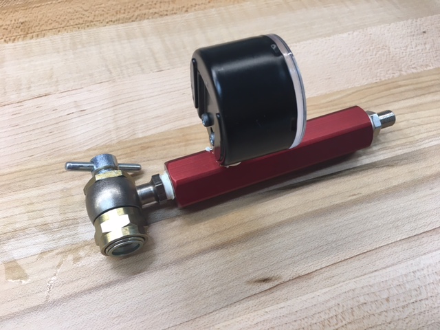
The front suspension was shipped in a suboptimal configuration. As can be seen in the picture to the right both the shock absorber body and the hydraulic lift ram are sitting on the lower control arm.

This is not the best orientation because:

  • It increases un-sprung weight (i.e., they are between the spring and the tire).
  • The shock absorber reservoir hose (visible) and the hydraulic ram hose (not installed yet, green tape covering the hole) will bounce up and down with the suspension.
  • To replace the spring, you need to remove the top bolt which requires you to remove one of the upper control arm's mounting points. Since spring rates are often changed when tuning the suspension, this is not something that you want to make more difficult than it needs to be. 
  • The Penske logo is upside down;-)

I called Penske to check if the orientation mattered and they said that it would work either way, but that most people mount the body to the chassis (i.e., opposite of what was shipped). Flipping the orientation of the shock absorber and the lift ram reduces un-sprung weight, keeps all of the hoses stationary and simplifies replacing the spring. I'm not aware of any downside to this orientation so it's a mystery to me as to why the factory ships the suspension the way that they do.

Optimal shock and ram lift configuration

Even after reading all of the documentation, I wasn't sure how to remove the springs. I called Allan who has built 20+ cars and he indicated that he couldn't figure it either and had to call them -- so, I guess my man card is in tack;-) In any event, it's very simple. You insert something with a 0.25" diameter (I used a pin punch) into one of the holes in the spring retainer and rotate it counter clockwise.

Penske offers the TL-76W tool for $22.50 which will work a little better than the punch. Steve at Penske also told me that when I reinstalled the spring retainer to "Tighten it until it was snug and then a little more -- probably less that 20 lb.-ft."

The lift ram can be oriented with the bleed port at the top or at the bottom. It is easier to bleed the air our of the system if the bleed port is at the top, so I went with that orientation.

Machined Uprights and Hubs

I took the uprights and hubs to a local machine shop and they came out great. As you can see in the first picture a large rotary table was used to remove the lip on the upright that was preventing the hub from being mounted. A very small chamfer was also added to the opening so that the flange would sit flat. The four threaded holes in the rectangular flange were also drilled to make them clearance holes. The machinist said it was as tough as any metal he's ever drilled.

The housing that bolts to the upright has an electroless nickel finish that should hold up well to the elements. They didn't use nickel on the wheel flange because it would have changed the dimensions on the bearing surfaces and masking was prohibitively expensive. It's a chromemoly forging and won't flash rust like a mild steel part does. I'll just apply some Boeshield T-9  to both surfaces.

I also confirmed that there are 47 teeth on the reluctor... the primary reason for upgrading the hubs.

Hubs and Ball Joints

The Hoosier hubs arrived. As expected they are really nicely machined and very robust. The hub on the left is what came with the kit. It's made in the USA and better than the OEM one its based on. The only reason that I'm upgrading it is because I wanted a reluctor for traction/launch control.

The hub on the right is from Hoosier. It's a lot longer due to bigger bearings and the addition of the reluctor, sensor and the electrical connector. Also note how much thicker the flanges are; the round wheel flange is 0.5" vs. 0.3" and the rectangular upright flange is 0.46" vs. 0.32". The rectangular flange has threaded rather than clearance holes, so they'll have to be drilled. Interestingly the wheel flange has holes to support both press in and screw in studs. This is possible because the flange doesn't have the three large holes the OEM flanges have.

I tried to remove the uprights so that the lip mentioned in the previous post can be machined. The ball joints were stuck tight. It seems that many people beat on them with a hammer (not on this suspension!) or use a pickle fork, but I found this Ball Joint Separator from Harbor Freight. While it's not something I'm going to use very often it's worth $21.99. This video does a great job explaining how to use it.