Pedals

72-603_front_wide1-500x500.jpg

The kit came with a beautiful set of Tilton 72-603 pedals. As you'd expect from a premium racing pedal assembly they are well engineered and massively configurable. The latter being a bit of an issue as the instructions merely state that "pedal position is highly dependent on the driver's preference" and you're looking at bunch of parts on the bench.

The first step is to mount the pedals. The brake pedal is wider than the gas and clutch pedals -- makes sense as the most important thing in any car is stopping. Each pedal can be installed in one of two orientations that provide different mechanical ratios. I wasn't sure which I would prefer so I just picked one. In addition each pedal can be installed in one of two bolt positions which will change the height by 1/2". Since I have small feet, I chose the shorter option -- don't go there, small feet means small shoes and that the body can expend resources growing other appendages. In any event all of these settings will be easy to change even when the pedals are mounted in the car.

The next step was to determine how the pedals should be positioned. With a 1,000 HP motor in a very light car you want the throttle pedal throw to be as long as possible, so I adjusted the min and max limits accordingly.

Next I installed the clutch, front brake and rear brake master cylinders. I upgraded the Wilwood master cylinders to Tiltons because I believe the Tiltons are superior and they use a -4 AN fitting for the reservoir feed rather that a rubber hose and barb, and they have an additional -3 AN fitting on the pressure side which will allow me to cleanly install pressure sensors. Interestingly the front break master cylinder is ¾” and the rear is 7/8". Why? Well during braking a car's momentum shifts forward so more braking is done by the front brakes. So shouldn't the front master cylinder be bigger? Nope, for the same amount of pedal travel the smaller cylinder will generate more pressure.

Next I ensured that the front/back brake bias balance bar was set to 50/50 which means that I actually have front bias because the front cylinder is smaller. Note that I will add a an adjustment knob so that I can change the bias while the car is in  motion. I then positioned the brake pedal so that it was closer to the driver than the throttle to facilitate heal-and-toe shifting. I think it's right, but I won't know for sure until I drive the car. To achieve this I had to cut the threaded shaft on both the front and rear brake master cylinders. As can be seen in the picture to the right, the Jet belt sander does a great job at cleaning up the cuts.

Throttle Linkage & Throttle Position Sensor

Since the car is drive by wire (DBW) I purchased Titlton's throttle linkage kit. Like everything Tilton, it's very well made. However, I had an issue with the lock nut on the max travel stud hitting the bracket. I checked things out multiple times and figured that I could grind the bracket, but that didn't seem right for Tilton quality so I called their tech support and sent them some pictures. They called me back about an hour later. Apparently the holes in the bottom of the bracket are asymmetrical and the shaft had been installed backwards at the factory, thus moving the bracket slightly towards the throttle pedal. The picture on the left shows the asymmetrical bottom and the picture on the right shows the symmetrical top. After taking it apart and reassembling it everything was fine.

The bracket is designed for a Penny & Giles TPS280DP sensor. Apparently it’s a very nice hall effect sensor, tested to 60 million operations, 12-bit resolution, zero signal degradation over the lifetime of the sensor, sealed to withstand high pressure wash-downs (IP69K), dual outputs, etc.

All wonderful, but after spending hours of googling around I found all types of press releases, specs, etc., but no place to buy it online. After sending a bunch of emails to the manufacturer and re-sellers I received one quote: $250.04 and “approximately 6-8 weeks” delivery --  two months, really?

When I asked about the lead time for a replacement in case of failure, they suggested that I buy two! Clearly they forgot to mention that parts of it were made of unobtainium. After posting in the GT40s forum one of the members to me that Jenvey Dynamics white labeled as part number TP8LH. The LH indicates that the throttle value increases in the anti-clock-wise direction which is British for counter-clock-wise. In any event, I found an online retailer in the USA which offered it for $90 less.

Reservoir Connections

The reservoir connections were plumbed with -4 AN couplers and crush washers. The hose and fittings will be done at a later time.

Pressure Sensors

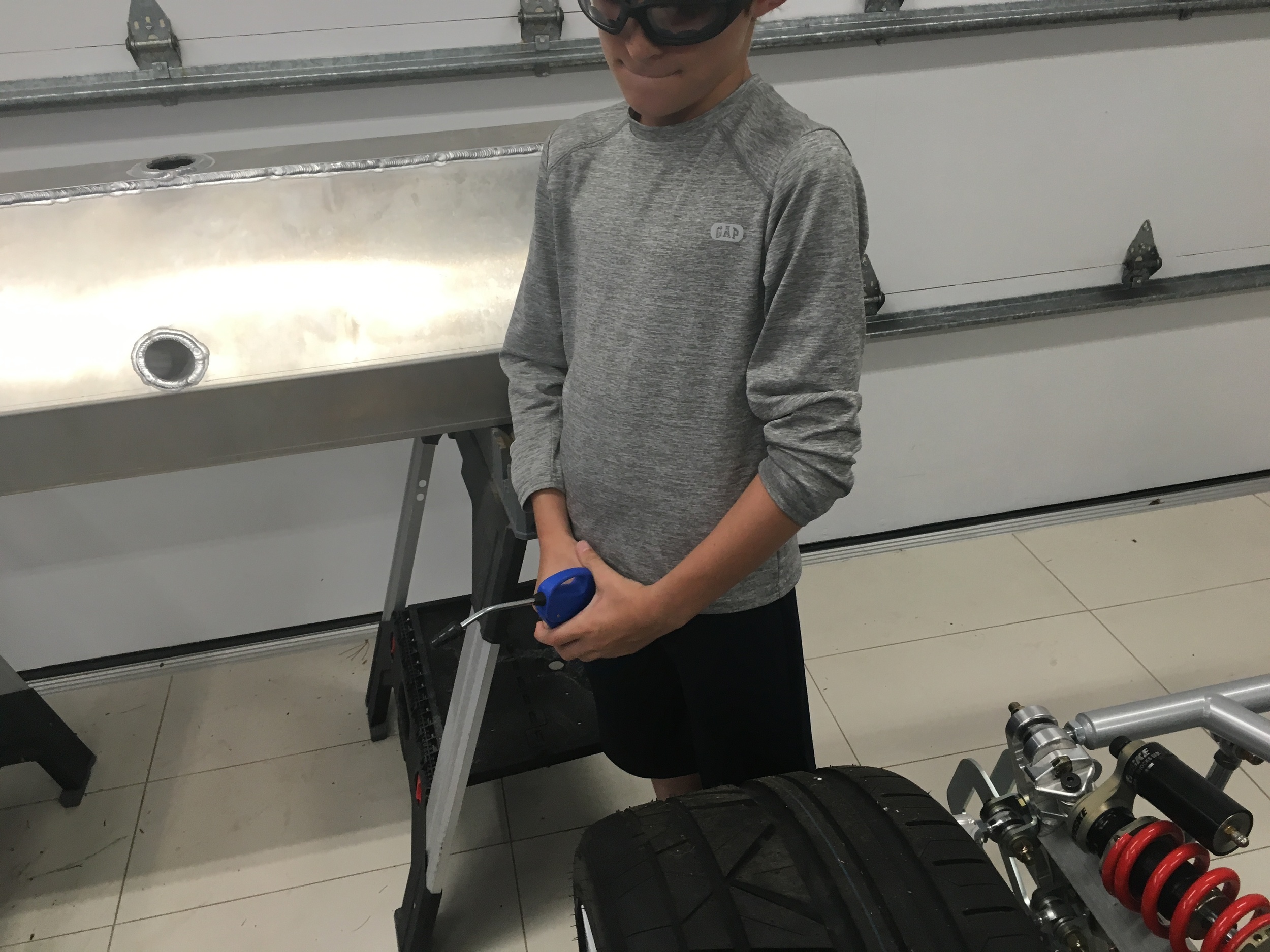
I replaced the supplied brake pressure switch with three high-end pressure transducers on the font brake, rear brake and clutch master cylinders. This will enable me to log the values and have the MoTec Power Distribution Unit (PDU) take actions based on the pressure. The connection required a special -3 AN Male to 1/8" NPT Female connector into the extra -3 AN port on top of the cylinders. The pressure sensor required a 1 1/16" wrench to tighten, which is the first time that I've used that wrench. Ironic that the tiny pressure sensor required a wrench much larger than all of the manly suspension pieces.

All of this resulted in a very clean installation.

New Friends

I've met a lot of great people chasing the SL-C dream and two of them, Will and Peter, stayed over for a couple of days to help out with the car. We discussed many things, found issues with parts and discovered some big challenges to think through. For example, the supercharger intake tube interferes with the gas fill tube (car kinda needs gas), the condenser was damaged during shipping, the evaporator won't fit due to the custom track-day bars, the banjo couplings on the brake calipers needs to be machined to fit BremboGTs which are much larger than the stock brakes, etc. Even these set backs represent progress because you can't solve them until you find them!

On the one step forward side, we cut an opening in the tail for the rear window. While the window hasn't been fitted yet, you can in the second picture that the carbon fiber vents have been fitted (but not installed). They are beautiful pieces and help mitigate one of the largest challenges with a mid-engine car -- keeping the engine cool. Cinder inspected them and she certainly thinks they're cool!

We were also able to get the majority of hard brakes lines and clutch line mounted to the chassis with some nice red clips from Made 4 U Products. The passenger-side rear brake line needs to be cut and flared for a better fit and the line running behind the fuel tank will need more clips installed, but that will have to wait until the engine is pulled.

Fuel Tank Mounted

It's important to isolate the fuel tank from the chassis to reduce stress and vibration that can lead to cracks or other failures. It's also critical that it stays put in the event of an impact or a roll over. It stores and 19.2 gallons which equates to about 116 pounds which, when multiplied by whatever Δv (hopefully small), means that you want to ensure that it's well mounted.

The tank is positioned as far as possible to the passenger side to provide better weight distribution when there is no passenger (I'm also a little heavier than my wife!)

I was going to fabricate brackets from 90° angle aluminum, but I found some nice ones from 80/20 Inc. They are clear annodized and gusseted for extra strength.

The self-adhesive rubber was cut to size and applied to the chassis and brackets. Two small brackets were installed to support the lower rear of the tank. Since they partially sit on welds, the bottoms needed to be machined for them to sit flat. Two large brackets were mounted on top of the tank and one large bracket was installed on the side of the tank to keep the tank from sliding to the driver's side (the passenger's side of the tank is stopped by the chassis).

I think that I'm going to install one more large bracket on the large cross member to prevent the top of the tank from tilting backwards, but I'll need to pull the engine to gain access.

Man Card Revoked?

Over vacation, whenever I was taking too long to get in the chilly ocean water, my daughter would threaten to revoke my man card. Today that got me to pondering,

"If I get as excited about garage cabinets as my wife does about kitchen cabinets, is my man card going to be revoked?"

I'm sure you're wondering what the catalyst was for this 'deep' introspection.. it was Joe from Motorhead Extraordinaire who installed a new set of Lista cabinets. They support 440 pounds per drawer and are what the aerospace guys use, so I did an appropriate number of Tool Man Tim grunts... and, yeah the man card is safe for today LOL.

The bench height resulted in the drill press being too tall (top right picture), so I cut the pole by a little over 8". I also had to modify the the table rack to fit in the reduced space. The 14" Metal Devil blade cut them both like butter... look how smooth the cut was in the bottom left picture (that's without any filing). I only needed to do minor deburring and beveling. Nothing like having the right tools.

Bubbles

Having cleaned the fuel tank and installed the fuel-level sender, the next step was to pressure test it. The tank has as a lot of TIG welding and if there’s a leak you want to find it before you install it and fill it with gas. I temporarily plumbed a Schrader value into the top left NPT port, a pressure gauge to into the top right NPT port and a  ½” NPT to -10 AN fitting with a cap in the bottom port. I pressurized the tank to 5 psi and went to dinner. When I returned the tank was down to 3 psi – I had a slow leak.

To find the leak, I mixed dish soap with a little water and brushed it on all of the seams. Fortunately, none of the tank seams leaked, but all of the NPT ports were leaking. I was surprised and how many bubbles a slow leak produced. I tightened the brass fittings as much as I dared, but they still leaked. While NPT threads are tapered, they don’t have a flare like you’d find in an AN fitting and they are often sealed with Teflon tape. However, Teflon tape isn’t compatible with fuel and if you’re not careful a piece might wind up in a fuel injector. Instead, I bought some Permatex Aviation Form-A-Gasket, applied it to the treads and no leaks! Next step is to install the tank.

Good Project for Hot Day

It was hot and humid which presented a good opportunity to remove all metal chips and dust from the fuel tank. The NPT openings were sealed with brass plugs and the fuel filler opening was sealed with this rubber end cap from Home Depot. The tank was filled with water via fuel-level sender opening and Connor was recruited help spill it out of the tank. The first rinse didn't result in any debris that I could see, but my OCD required that do it three times. Connor was having fun and he demanded that we do it a fourth time, so it's one clean tank.

When then tank was dry, I poured several cups of acetone into the tank and sloshed it around on all sides to remove any residue. 

The fuel-level sender provided in the kit is very nice. It is customized to take the unique shape of the tank into account and it measures capacitance so it has no  moving parts. The sender was mounted with five 10-24 bolts, #10 washers and the supplied cork gasket. Loctite 442 (aka blue Loctite), which is compatible with fuel, was applied to the threads.

Vacation and RPVs

I’ve been on vacation and I haven’t had any time to work on the car. However, I have been doing lots of research and ordering things. This of course causes a debate with my son when I try to get him off the iPad. He just doesn't see the difference between "research" and playing games.

Everything in the SL-C is low and the brake master cylinders are no exception. They are mounted below the brake calipers and gravity will cause brake fluid from the calipers to drain back into the master cylinder which causes excessive caliper piston retraction which results in a longer brake pedal stroke. To solve this problem, a residual pressure valve (RPV) is installed. A 2 psi RPV is firm enough to prevent fluid from flowing back but not so firm as to extend the caliper piston which would cause the brakes to drag. Since there are two master cylinders (front and rear) two valves are needed. The kit came with valves, but some builders have had issues with them leaking so I upgraded them to Wilwoods.

Fuel Tank: Part 1

I finally got around to removing the cage, interior tub and back panel to get access to the fuel tank. As with many Superlite parts, it's custom made and beautifully TIG welded. The pipe passing through the middle of the tank (you can see all of the way through it in the first picture) provides the straightest possible path for the shift cables... it's a mid-engine car and the drivetrain is behind the driver. It angles downwards from the driver side towards the passenger side.

The first step was to tap five 10-24 holes in the fuel level sender flange... and then start ordering lots of parts to start connecting things.

Seat Brackets

I wanted to see what it feels like to sit in the car so I installed the seat brackets. I'm likely going to upgrade to Tillet carbon fiber T5s in the future, but these will work for now. Comments at bottom of each picture.

Body Dolly

I removed the body today and built a dolly so that I can move it around. I was going to stand the sections up to save space, but I didn't want to store it in a way that might cause the body to deform. I also love looking at the car and I wanted it around to inspire me, so I built a whole-car dolly out of 2x 4's and 3/4" plywood sitting on six lockable caster. It raises the body a bit so it doesn't look quite as bad ass...

Note that I ran out of time and the nose and tail aren't sitting right... I'll fix that later. Can you find the dog in the picture below?

It's Here!

My car was delivered last week... about as good as Xmas morning when I got a Six Million Dollar Man action figure, a Guns of Navarone mountain and a bunch of military/automotive models. Reflecting on it, that’s a glorified doll, a multi-story doll house and models that required glue that causes brain damage if sniffed… what the hell were my parents thinking?

In any event, there was lots of tape residue on the car. The more options, the more residue. I did a bake off between Goo Gone, Goof Off and WD-40. Goof Off worked the best.

Father / Son Boondoogle

My son had vacation this week, my daughter had school and my wife was in Europe. What to do with a 10-year old? Take him to California to spend some time with the grandparents. For some reason I couldn't find a direct flight from Boston to San Francisco so I had spend a night in Detroit on the way there... so we went to the Henry Ford Museum.. and along the way we somehow stumbled into Superlite Cars / RCR...

MoTec Quality

The MoTec ECU, GPS transceiver and digital display were delivered today. The quality of the case is outstanding not to mention the display itself. MoTec appears to have their act together with respect to software and product modules. Many of the features in their embedded devices are activated via software keys. I assume the branded USB stick in the foreground does exactly that. It will be quite some time before I know for certain if MoTec is as good as their reputation, but so far I'm impressed.