The pneumatic shift servo is powered by a Shiftec Air Power Source (APS) which has a max operating pressure of 9.8 bar (142 psi). The servo’s ram connects to the shift lever via a 1/4”-28 rod end. I wanted a high-quality bolt without any threads in shear so I purchased an AN bolt with a 0.688” grip from Pegasus Auto Racing. The advantages of AN bolts are that the grip lengths are available in 1/8” increments, they are less brittle than SAE bolts and, so long as you don’t purchase a counterfeit, they are manufactured to a high standard, which is why you purchase them from a place like Pegasus, Aircraft Spruce, McMaster, etc. The shift lever’s clevis was too tight to accommodate misalignment washers so I used two thin (0.032”) AN washers.
The servo’s other side is an M8 rod end. I used two misalignment washers and an aluminum spacer that I machined on the lathe and to ensure that the shift servo was orthogonal to the shift arm. I then fabricated a bracket out of 1/4” 6061 aluminum to place the shift servo’s mounting bolt in double shear. It required an offset bend which is a little tricky to get perfect.
Bend lines scribed in layout dye on the edge and marked in pen on the actual bend location. The distance between the bend lines is 4.407”. Note the 1/8” aluminum scraps taped in place to prevent the upper die from damaging the material.
I measured how far the outer misalignment washer was from the transaxle, decided that I wanted the bend lines to be one inch from the center of the mounting holes which allowed me to determine the length of the base of the triangle. I then used the Pythagorean theorem to figure out the distance between the bend lines (i.e., the hypotenuse) and the sine function to figure out the bend angle. My middle school math teacher would be happy to know that the SOH CAH TOA mnemonic stuck and I didn’t need to Google it — well actually I did just to make sure, but I had it right.
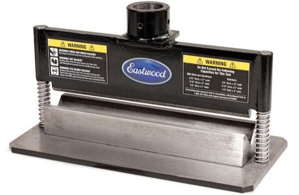
I purchased an Eastwood press brake attachment that fits my 20-ton Harbor Freight hydraulic press. The advantage over the garage-made dies that I used in a previous post is that the top and bottom dies are automatically aligned and the unit is heavy which makes it easy to use a square to align the material being bent. The downside is that the upper die is pointed rather than a piece of 3/4” round bar which gouges 1/4” aluminum.
I had calculated the bend angle to be 16.2 degrees so I used a digital angle gauge to achieve 9.2 degrees. Since both sides are being equally bent and the gauge only measures one side I divided the number by two and then added one degree for spring back. While the trig is exact it doesn’t take into account the bend radius and that the material stretches when bent. After experimenting with a few pieces I determined that the target angle should be 10 degrees and that a piece of 1/8” of scrap aluminum placed on top prevented the upper die from leaving a crease in the part.
I found that leaving the ends long allowed me to easily determine if they were parallel. Once the piece was bent I used a belt sander to remove the deformation on the sides caused by the bending process. Not doing so will result in the vice jaws only squeezing on bulges which will throw off digital readout (DRO) measurements. Worst the bulges aren’t equal which means that the largest set will act as a pivot point which can cause the part to spring upwards and out of the vice when being machined. This not not only wrecks the part, but it can create a dangerous situation. I had that happen with a previous part and I know better now.
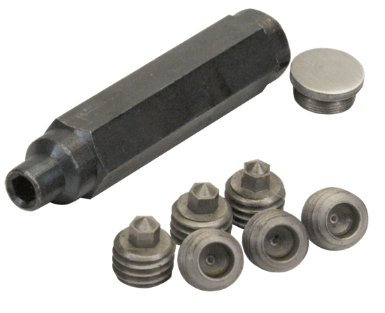
Transfer screws; the handle stores the screws and is used to thread them the desired distance into the hole (i.e., so that the pointed tip barely protrudes from the hole)
I then drilled an M8 hole in the bracket and mounted the servo. The next challenge was to precisely determine where the the second mounting hole should be drilled. This would be difficult to achieve by measuring. Instead, I applied layout dye to the back of the bracket and used a transfer screw to scribe a short ark. The intersection of that ark and the midpoint of bracket was the exact location of the hole. The result was pretty much zero slop even before the screws are tightened.
The next step was to lighten the bracket with holes, slots and rounded ends.
All of the parts. The bracket and spacer are custom.
Shift servo and bracket mounted to bosses on the transaxle
The offset bend is apparent in this picture
The next step is to figure out how to route the wires and the air supply hose.