To optimize cooling, it’s imperative that all air that flows into the radiator inlet in the body is forced through the condenser and radiator. This is best accomplished via an air-tight, diverging duct that provides a smooth transition from the opening in the body to the outer edges of the radiator core. Specifically, it’s preferable that the air isn’t allowed to contact the underside of the nose, the vertical panels that support the radiator nor the radiator’s side tanks.
There’s a fair amount going on inside of the duct; condenser lines, nose hinges, splitter support rods and a tow hook, so it took a while to figure out the best approach. The first step was the top of the duct. The triangular section of the nose subframe was designed to pitch downwards from the top of the radiator to the top of the inlet in the body. It stiffens the subframe while providing a robust mount for the top of the inlet duct and the tow hook (the car be jacked on the car on tow hook). The top of the duct was made from four parts:
Two triangular inserts.
A cover between the nose subframe and the radiator.
A cover that is attached to and pivots with the nose. When closed, it seals the body to subframe.
The video below shows prototype parts and the pivoting motion.

The triangular inserts sit on flanges covered with thin strips of rubber (not shown)

The triangular inserts were formed using custom dies. They were cut from 1/4” steel plate on a CNC plasma table, the edges were dressed with files and a pencil belt sander, the panels were annealed in the areas to be shaped and a hydraulic press was used to emboss the shape.
A closeout panel was fabricated to seal between the nose subframe crossbar and the top edge of the radiator. It also seals the top of the condenser.
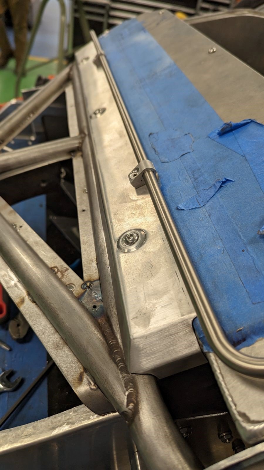
It was tempting to use the vertical panels that support the radiator as the sides of the duct, but they’re not well suited for that purpose. They’re several inches wider than the both the inlet and the radiator core which will result in the air expanding beyond the radiator core, colliding with the nose hinge standoffs and hitting the radiator side tanks head on. This makes it more difficult to seal the sides of the radiator, increases drag and I assume has a deleterious effect on mass airflow through the radiator core. Since the pivoting half of the nose hinge is bolted to the side of inlet in the body, the ideal location for the duct side is between the fixed and pivoting halves of the hinge. The issue with that approach is that the hinge would bind. The solution was to manually machine a 0.062” pocket into the fixed half of the hinge to accommodate the side panel.

0.062” pocket machined into the interior face of the stationary part of the hinge. Note that the leading and top edges were left full thickness which facilitates air tightness and maintains aesthetics. It would have been a lot easier to design this pocket in CAD and have it CNC’d, but it came out great.
The splitter support rod tabs that had been welded to the subframe last year interfered with the top of the duct. Fortunately, they were only tacked into place so it was easy to cut/grind them off and fabricate a new set that cleared the duct.
Unlike the stock radiator which has very little in terms of vibration isolation, the custom radiator is supported via two rubber sandwich isolators per side. To maintain this level of isolation foam was used to seal the top and bottom of the duct and rubber flanges were used to seal the sides.

The stock vibration isolators (left/black) are small grommets and are next to useless. The custom radiator uses sandwich isolators (right/red) so it’s important to ensure that duct is properly isolated from the radiator and condenser.

An adjustable rubber flange (black) is notched around the condenser lines and is used to seal the sides of the duct to the face of the radiator while keeping the two isolated. The top and bottom are sealed with foam strips.
