I’ve retained BM-Technik Race Engineering (BMR) out of Germany to design and fabricate the harnesses for my car. They’re a top-tier firm focused on race teams, OEM hyper cars (I’ve seen a few of the projects, but they’re under NDA), vintage F1, etc. and a friend talked them into taking my project on.
The harness is a large project because I have a lot of electronics and, to keep everything as clean as possible, I’m subsuming all of the commercial harnesses (e.g., engine, climate, EPAS, brake booster, active dampers, active wing, parking brakes and exhaust cutouts) with the following bespoke ones:
Chassis
Engine
Front
Left-Front Hub
Right-Front Hub
Nose
Rear
Engine Cover
Left Door
Right Door
Motorsport harnesses are mostly a one-shot deal because they are sealed making it difficult or impossible to modify them. So, there’s a massive amount of upfront research and planning to have a fully detailed design for the 150+ devices that need to be wired. I’ve learned a lot of basics. For example, it’s important to arrange the sensor grounds so that you don’t share a sensor ground between a critical sensor and non-critical sensor because you don’t want a failure with a non-critical sensor’s wire to bring down the critical sensor.
The design effort was estimated at 300 hours which doesn’t include programming or labor to build the harnesses. To put that in perspective, Allan spent 1,200 hours on his most recent SL-C build which includes paint. Given the level of expertise and effort to design bespoke harness the handful of companies that can this are all bottle necked at the design phase so it’s not easy to get a slot. Stefan, who I introduced in a previous post, spent two weeks with me in Boston figuring out how to layout the harness, mounting the devices and taking careful measurements. He’s also the Systems Engineer for the Inter EuroPol team, which just won the LMP2 class at Le Mans for the second year in a row, so he’s constantly on the road and only able to work on my project between races. The best guys are always oversubscribed and it’s been a privilege to work with Stefan and the rest of team.
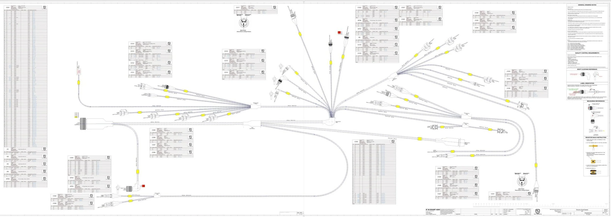
Engine harness PDF export from in Zuken E3. Each harness will have its own design sheet.
Stefan used Zuken E3 to design the harness. Apparently, it’s a high-end CAD package which runs about $30k/user/year and is used for everything up to nuclear subs. Fortunately, they provide PDF and Excel exports as well as a free read-only, viewer application to us mere mortals. The application enables you to interact with the design: trace wires, list all of the detailed part numbers, etc. While the chassis harness is the largest, the first harness we focused on was for the engine which connects to the chassis harness via a 128-pin autosport connector.
Contra-Helical Twisting
Motorsport harnesses utilize contra-helical twisting to maximize flexibility, reduce diameter and mitigate strain on the wires. With this approach, each successive layer of wires is twisted in the opposite direction of the previous layer. In a typical harness, the core has seven wires, with each successive layer adding seven additional wires (i.e., core=7, L1=14, L2=21, L3=28, etc.). However, the actual number of wires in a layer may vary to accommodate pre-twisted pairs or wires of different gauges. Optimizing which wires go in which layer requires a lot planning. Bulky cables (i.e., pre-twisted shielded pairs) are typically placed in the center to increase flexibility and the other layers are driven by the location of branches/transitions and the devices. Obviously, you’d rather not dig through multiple layers of wires that are continuing straight to pull out wires that are going into a transition to head in another direction. You’d prefer to have them on the outer layer. If you think of the harness as a tree, ideally the wires in the first branch in the outermost layer and the wires in last branch to be on the inner-most layer. However, you might have a wire that uses a splice to service both the first and last branch which complicates things.
In some cases it makes sense to not fully populate a layer so that wires can be moved to a subsequent layer. In this situation, non-conducting, white filler wires are added to achieve the perfect twist ratio and provide a smooth base for the next layer. Filler wires contain no copper so they are more flexible and weigh less than standard wires of the same gauge.
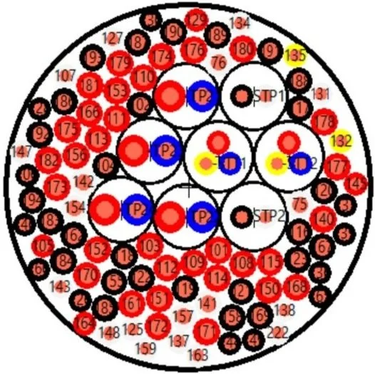
Engine harness cross section. The actual layers and filler wires are shown in another view.
Engine Harness Construction
While Stefan is having fun at the races, his younger brother Gustav has been working on the engine harness and he sent me the following pictures.
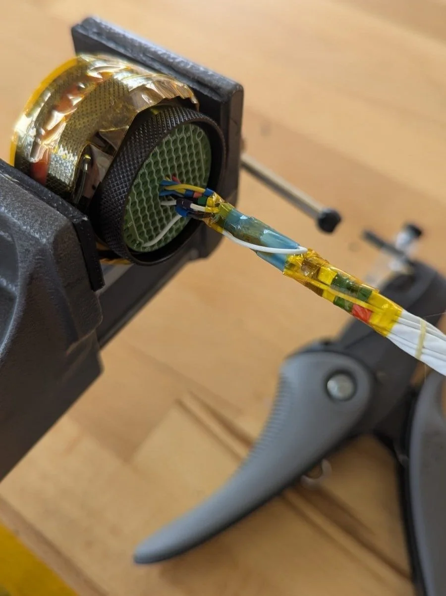
Core: The bulky pre-twisted cables were located in the center of the harness to keep it as flexible as possible. There are four composite cables; two shielded twisted pairs and two shielded triple pairs (i.e., a total of eight twisted pairs). To make the core as round as possible, eight standard wires were added before starting the first layer.
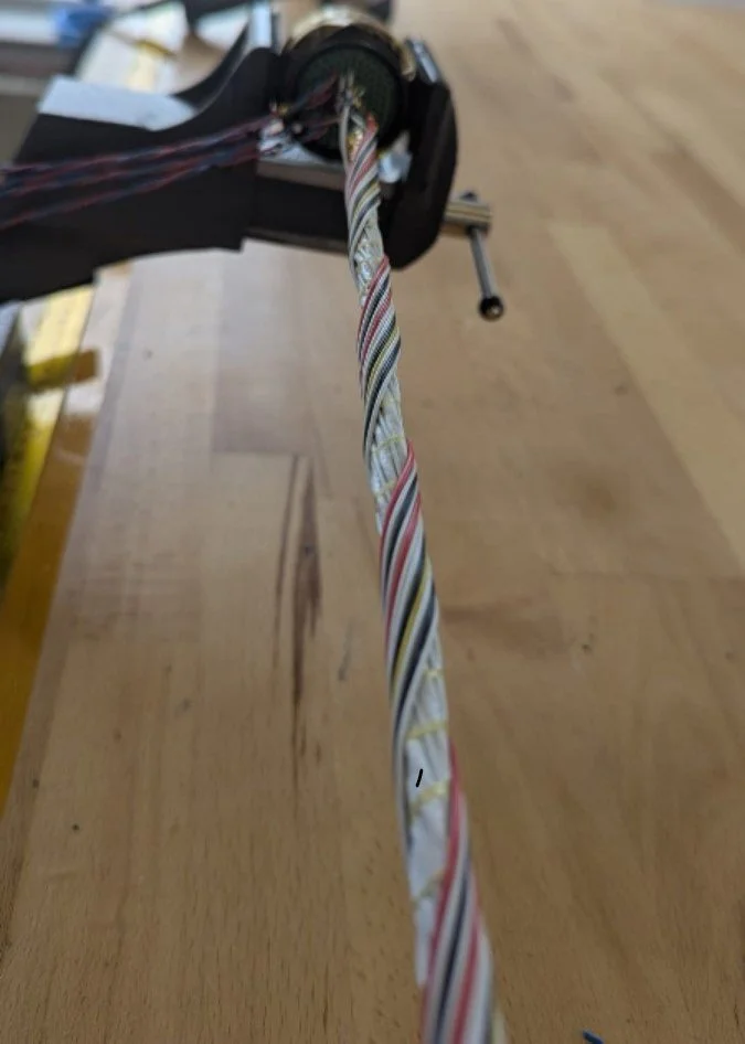
Layer 2: With a contra-helical harness each successive layer is twisted opposite to the direction of the previous layer. This maximizes flexibility and minimizes cross section. Note that the filler wire hasn’t been added yet so the outer layer has gaps.
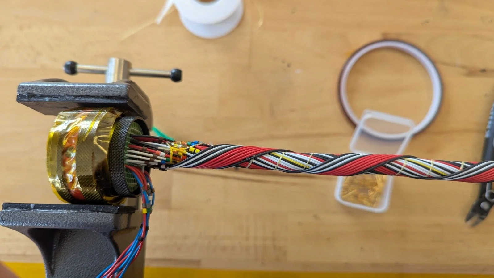
Layer 3: Approximately half way done. Note the identification markers that were discussed in the last blog post. They are the small colored pieces on the wires near the connector.
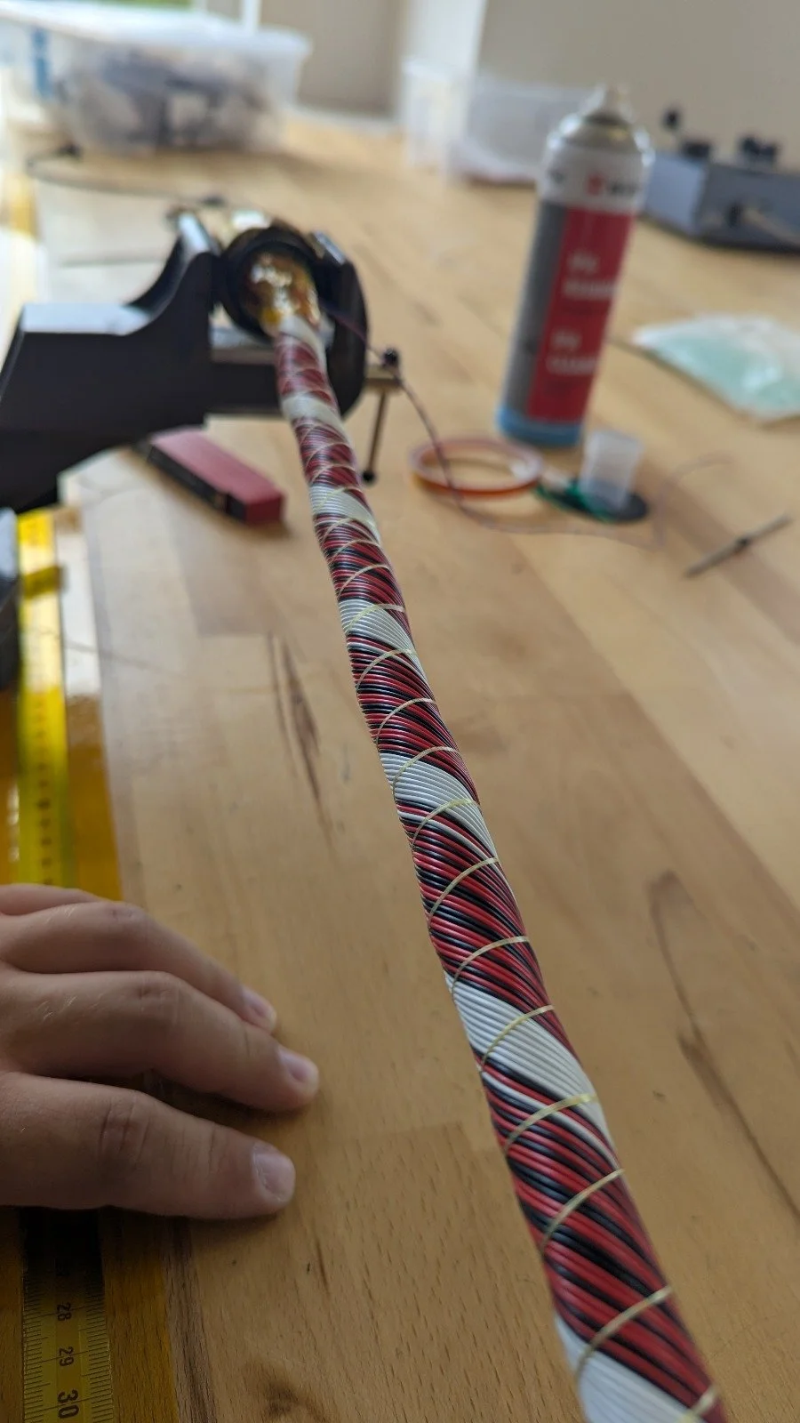
The filler wire has been added and the layer has been tightly wrapped with a Kevlar/Aramaid lacing cord to keep everything in place. The lacing cord is the single, flat, white thread that is wrapped in the opposite direction to the wires in the picture above.
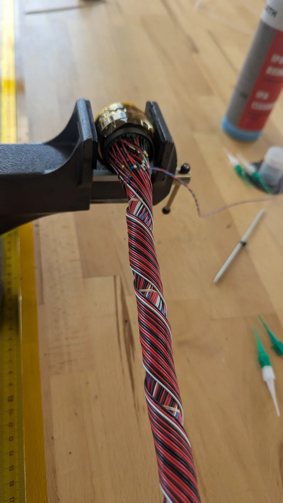
Filler wire has not been added to the outer layer yet. Note the identification markers that were discussed in the last blog post. They are the small colored pieces on the wires near the connector. Service loops were not added to reduce cost and the size of the boot. The mating 128-pin connector and the leaf connectors will have service loops in the advent that something needs to be modified.
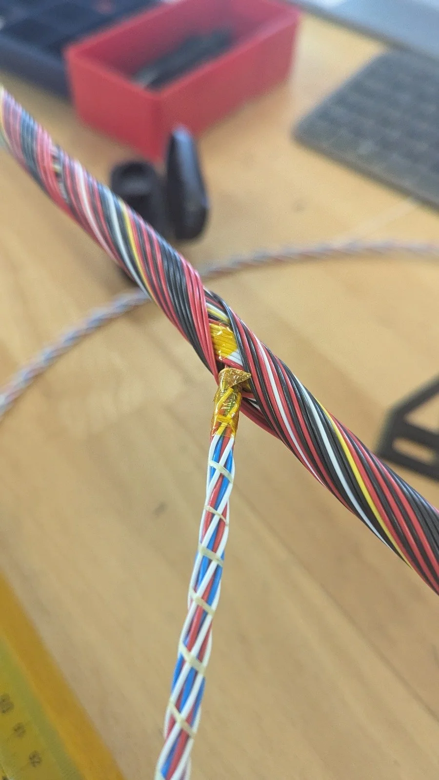
A transition
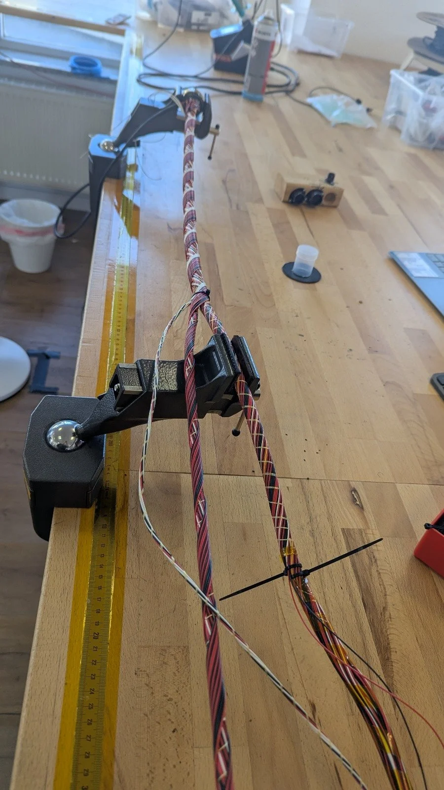
Multiple vices are used to maintain the twist on the transition legs until the lacing cord is applied. The filler wire hasn’t been added to the outer layer yet.
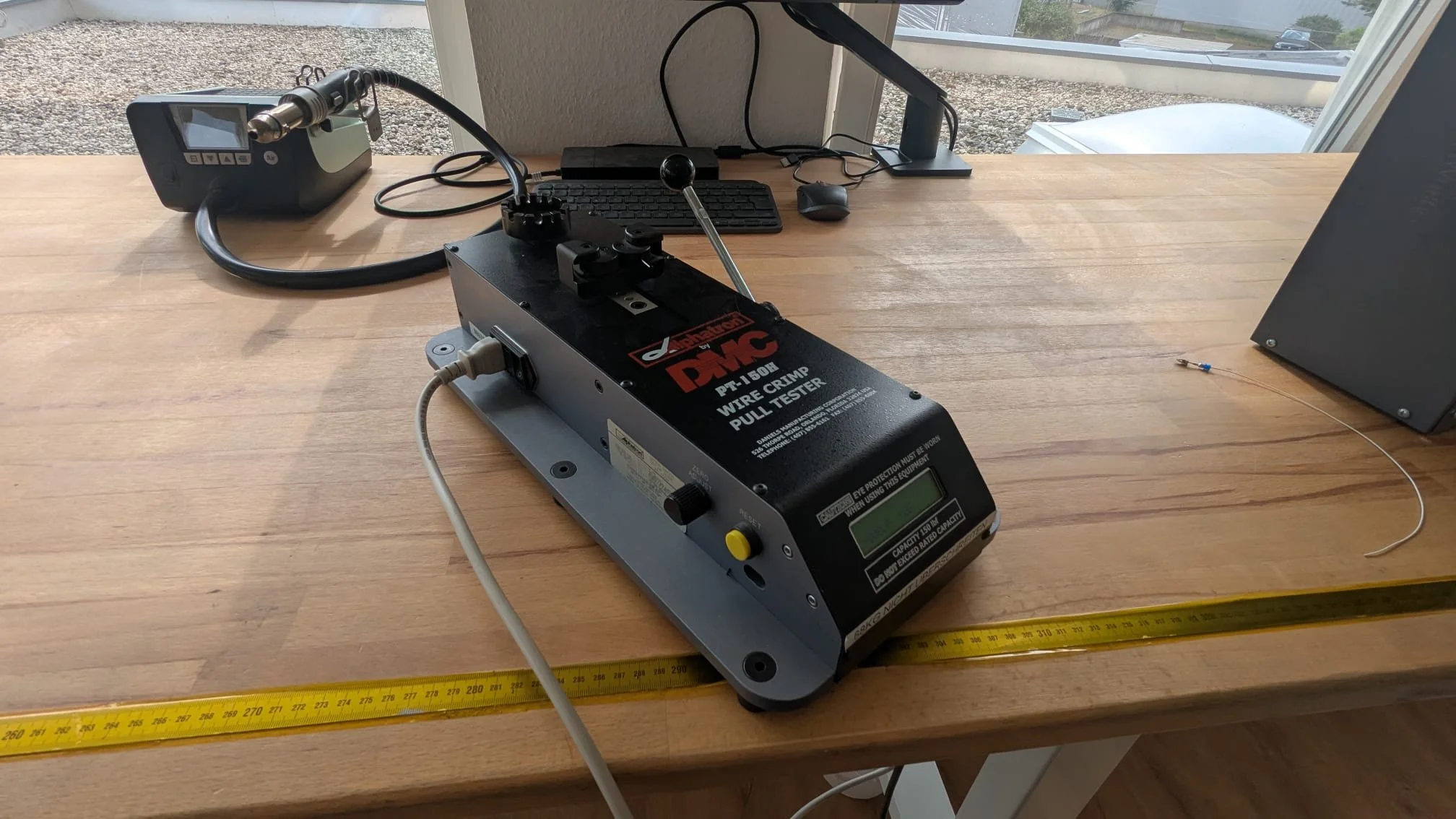
Crimping tools must be properly adjusted to achieve a proper crimp. The best way to achieve this is to crimp a sacrificial pin to a piece of scrap wire and validate it with a wire crimp pull tester. The pin is placed in an appropriate slot in the rotating turret, the wire is placed in the pulling mechanism and the operator slowly and evenly pulls on the lever until the crimp gives up or the wire snaps. The maximum applied force is displayed digitally. The motorsport spec is 9.8kg (21.6 lbs.). If the desired strength isn’t achieved, the crimping tool/die is adjusted and the process is repeated. For this reason, you want multiple spare pins so that the operator can dial in the settings. For example, my fuel injectors don’t utilize motorsport connectors, but after a couple of attempts Gustav was able to achieve 9.4kg (2% under the motorsport spec).
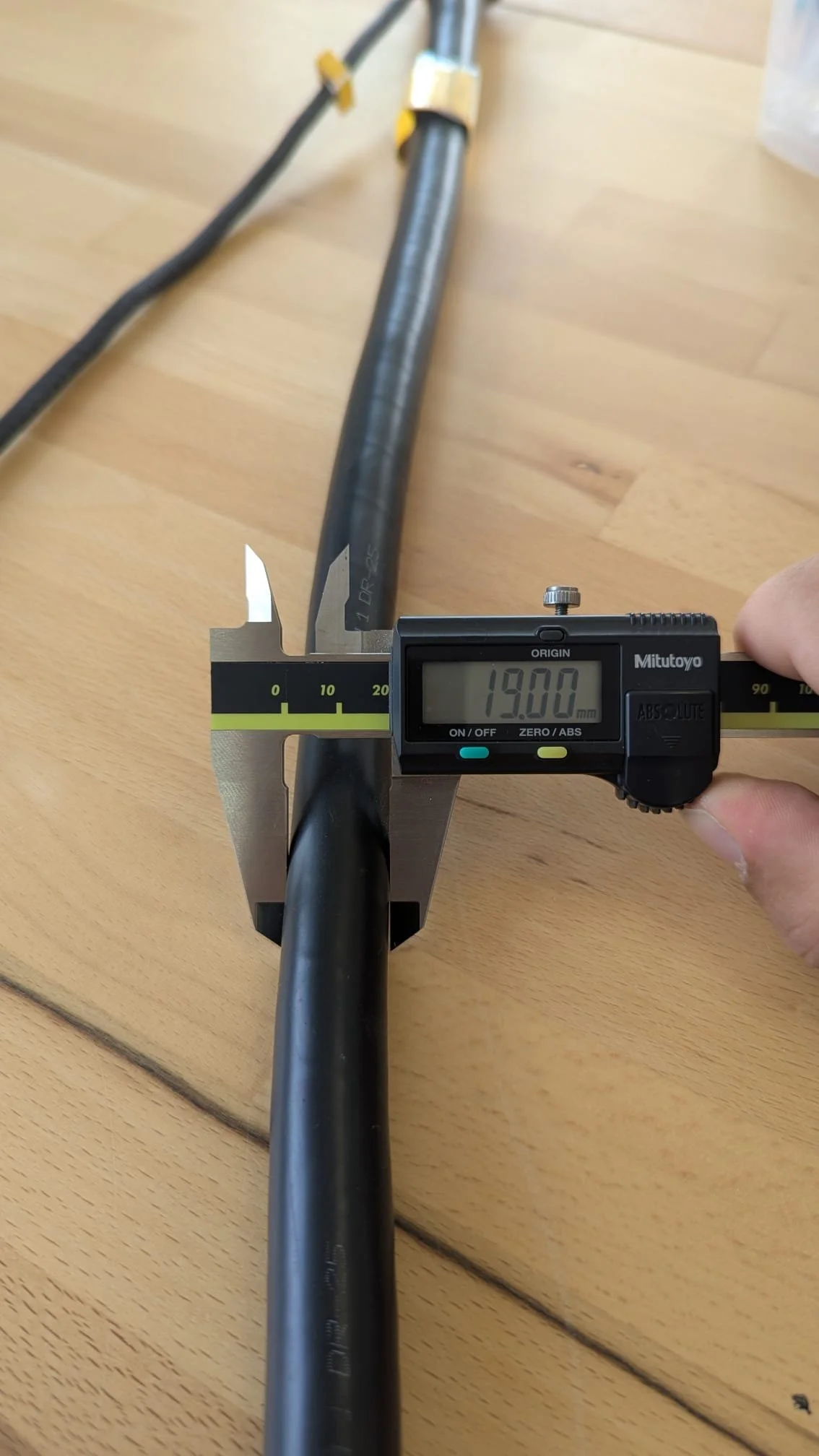
Raychem DR25 heat shrink tubing has been applied. It’s surprising that 180+ conductors, filler wires, multiple shields and the jacketing fit within a 19 mm (0.748”) diameter and remain flexible.
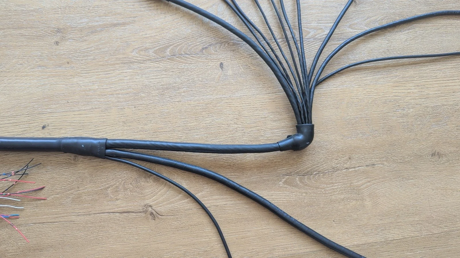
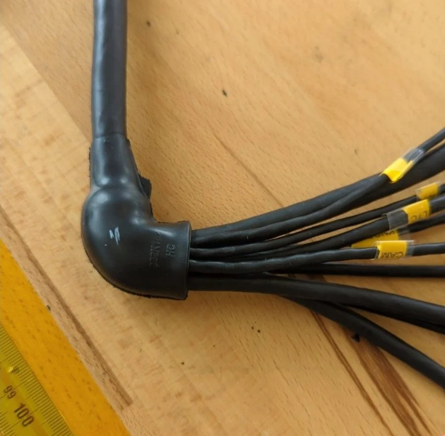
90-degree transition completed and yellow labels applied
Next Steps
The engine harness has been completed and pin-to-pin tested. Stefan is finalizing the design of the chassis and nose harnesses.