Rear Hoop Legs

I’ve removed/installed the cage many times and it’s a pretty quick and easy process. However, it’s a royal pain in the ass to install the rod ends that connect the rear legs to the top of the rear hoop. It takes me longer to install those two bolts, than it does to install the other 14 bolts combined. The issue is that the standard RCR suspension bracket is utilized which requires a high-misalignment rod end, two aluminum misalignment washers and a grade-8 washer to be crammed at an awkward angle. In fact, the body of one of my rod ends actually binds on the bracket. It’s difficult to get the washers and misalignment washers in place, let alone properly aligned, and if they fall you need to find them all because one might be in the supercharger, accessory or dry sump belt. Sometimes one hits the floor and rolls to God knows where and you can spend a lot of time looking for it on the floor or on the front engine dress. Last thing you want is foreign-object damage when you start the engine.

Conceptually this isn’t problem because the rear legs aren’t removed very often once the car is finished and you want everything tight.

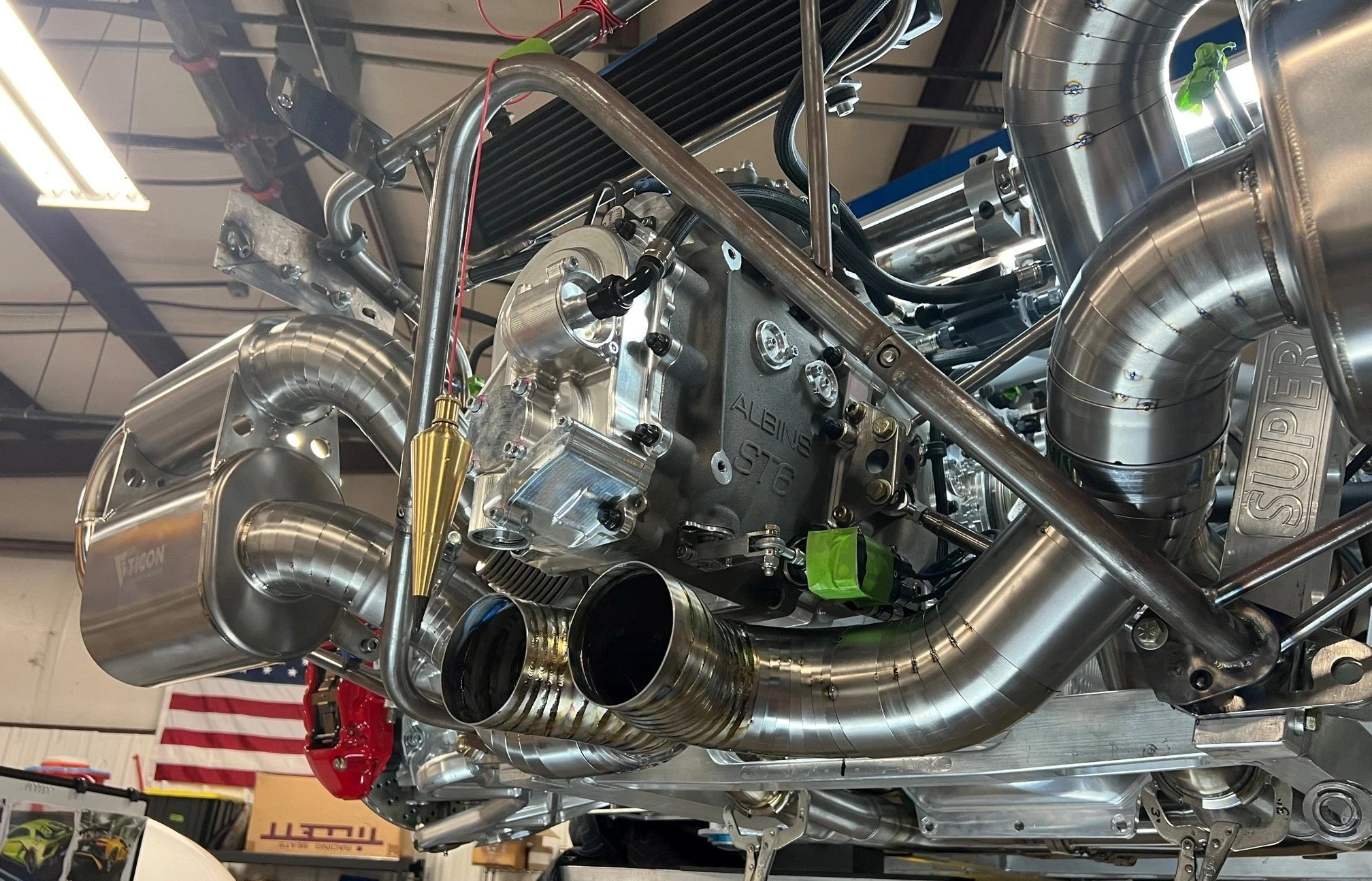
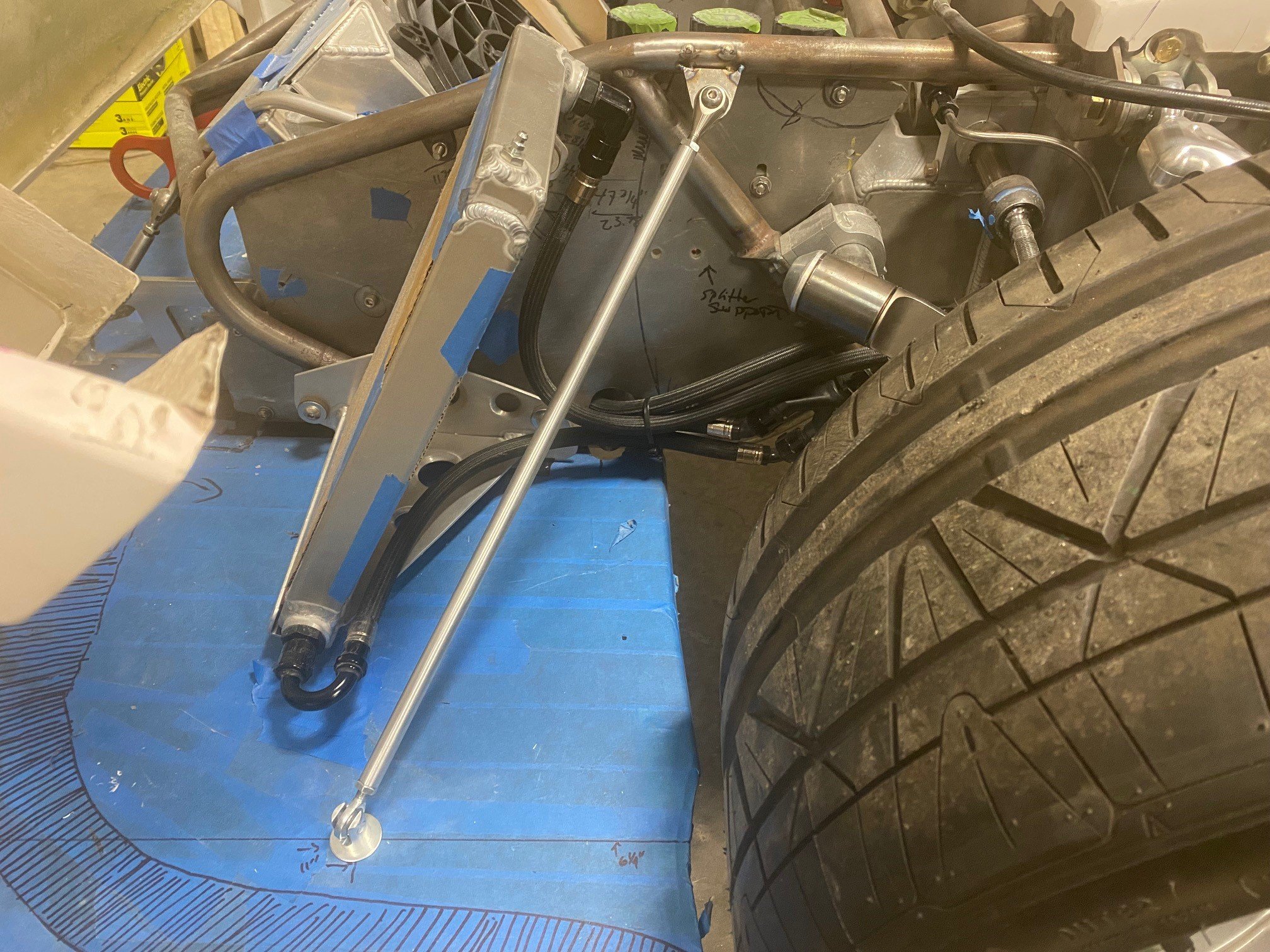
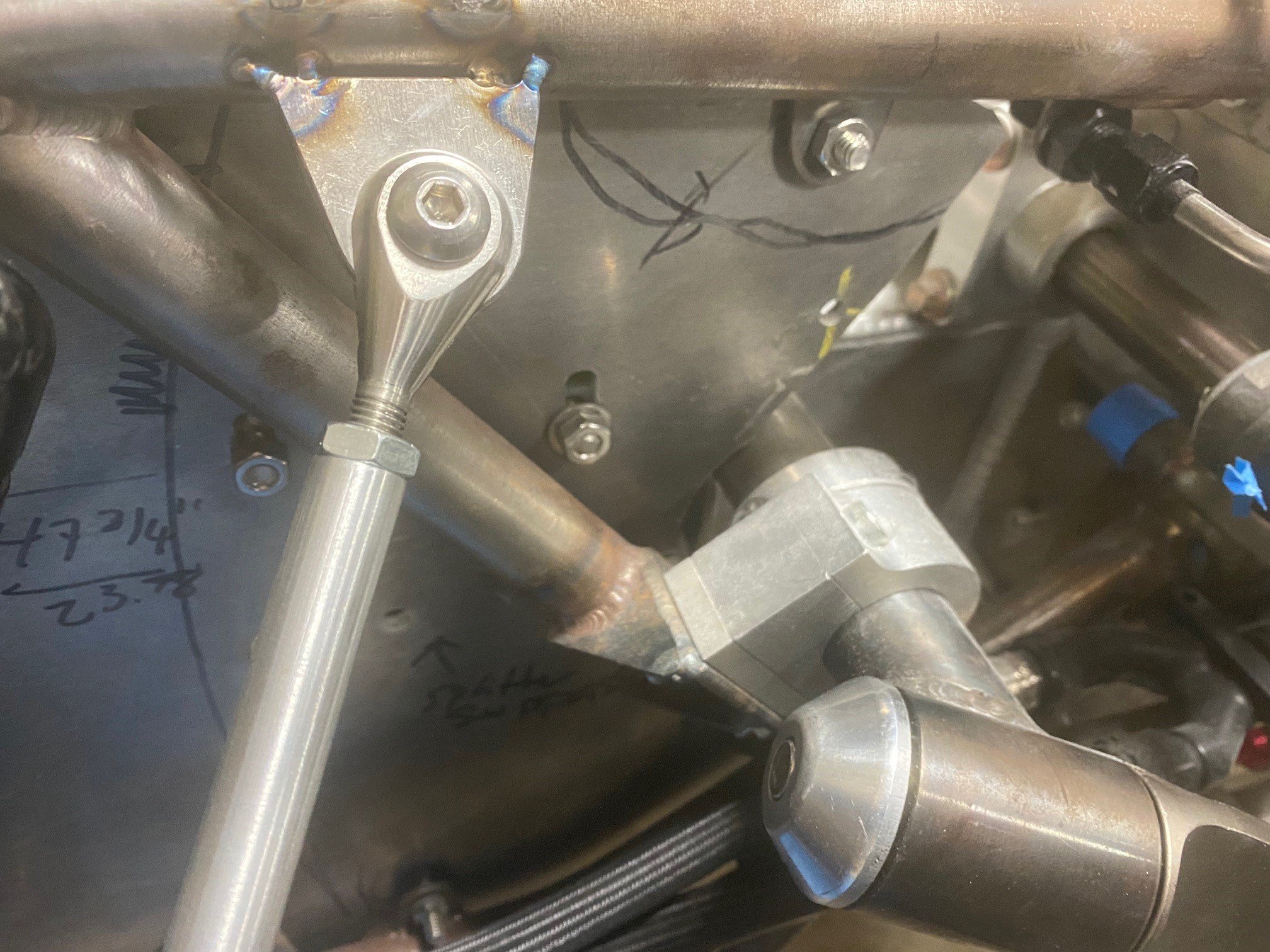
HOWEVER, as can be seen in the picture below, the body significantly overhands the rod ends and it’s somewhere between a nightmare and impossible to install things when the body is on. I struggle to install the rod ends and washers when the body is removed, I’m standing in the center of the cockpit and have prefect access to everything. With the body on, it would be easy to get the rod end installed, but the misalignment washers and grade 8 washer — NFW.

The carboard simulates the body. Note how far it overhangs the rod end

Given that I must remove the rear hoop legs to remove the engine and removing the body requires removing the doors, headliner, windshield (which I risk cracking) and removing and then reinstalling all of the sealing around the foot box, side pods and firewall, this is an untenable situation.

I considered welding a section of tube to a plate mounted to the firewall and using interlocking tube couplers to enable a section of the leg to be easily removed. The issue with that approach is that the tubes welded to the firewall would need to extend an inch or so past the body which, as shown above, extends well into the engine compartment and, at least in my case, would cause them to interfere with the supercharger during engine removal.

I settled on a three-part solution:

  1. Replace the 90-degree bracket with a custom bracket that matches the downward angle of the rear leg. This solves the root of the problem.

  2. Replace the 1/2” right-hand-thread (RHT) high-misalignment rod end, misalignment washers and grade-8 washer with a 3/4” RHT slot clevis. This is more robust, has three less parts to drop and there is zero struggle to line things up.

  3. Make the leg indexable by sectioning it and welding two 3/4” left-hand-thread (LHT) tube ends and a floating 3/4” grade-8 threaded rod. This makes it even easier to install/remove the leg and enables me to apply the perfect amount of preload.

The first step was to cut the tube a few inches from the Y-joint in a horizontal bandsaw to ensure a clean, square cut. I then cut the rod end off of the other end.

Rear hoop leg being sectioned with a horizontal bandsaw… no going back now!

I used high-quality 4130 tube ends. They project ~2.5x further into the tube than the stock pieces which provides more thread engagement and improved resistance to lateral loads. Abe showed me a fabrication technique that he learned during his days building high-HP drag chassis. He would bore four holes in the tube 90 degrees apart to add rosette welds in addition to the standard circumference/edge weld. While this increases the amount of weld contact, the primary purpose is to reduce lateral stresses on the edge weld by anchoring the inserted portion of the tube end to the tube. A center-cutting end mill works much better than a drill bit when creating a hole on a radius.

The bracket was a bit tricky to fabricate. Given the material thicknesses and size of the parts, I only designed a single slot and tab. The challenge was that the clevis plate is angled at 60 degrees which required the edge that mates with the base plate and the matching slot in the base plate to be beveled at 60 degrees. To accomplish this, I purchased an inexpensive (about $85) tilting vice. It’s not intended for milling, but I took very light cuts and it worked well. To reduce the size of the bracket the outside gusset was angled which required some grinding of the clevis and base plates.

The clevis plate is 3/8” (that’s what the slot clevis requires), the base plate is 1/4” (I didn’t want it to warp while welding the thick clevis plate), and the gussets are 0.190”, all of which were laser cut. The slot isn’t pretty because I wasn’t going for style points when filing the corners and the fit up was good for welding purposes.

The edge of the angled clevis plate being milled at 60 degrees (the 30 degrees indicated on the vice is the reverse angle)

The upper and lower edges of the laser-cut slot in base plate about to be milled at 60 degrees (the 30 degrees indicated on the vice is the reverse angle). The end mill left rounded corners which were manually filed square.

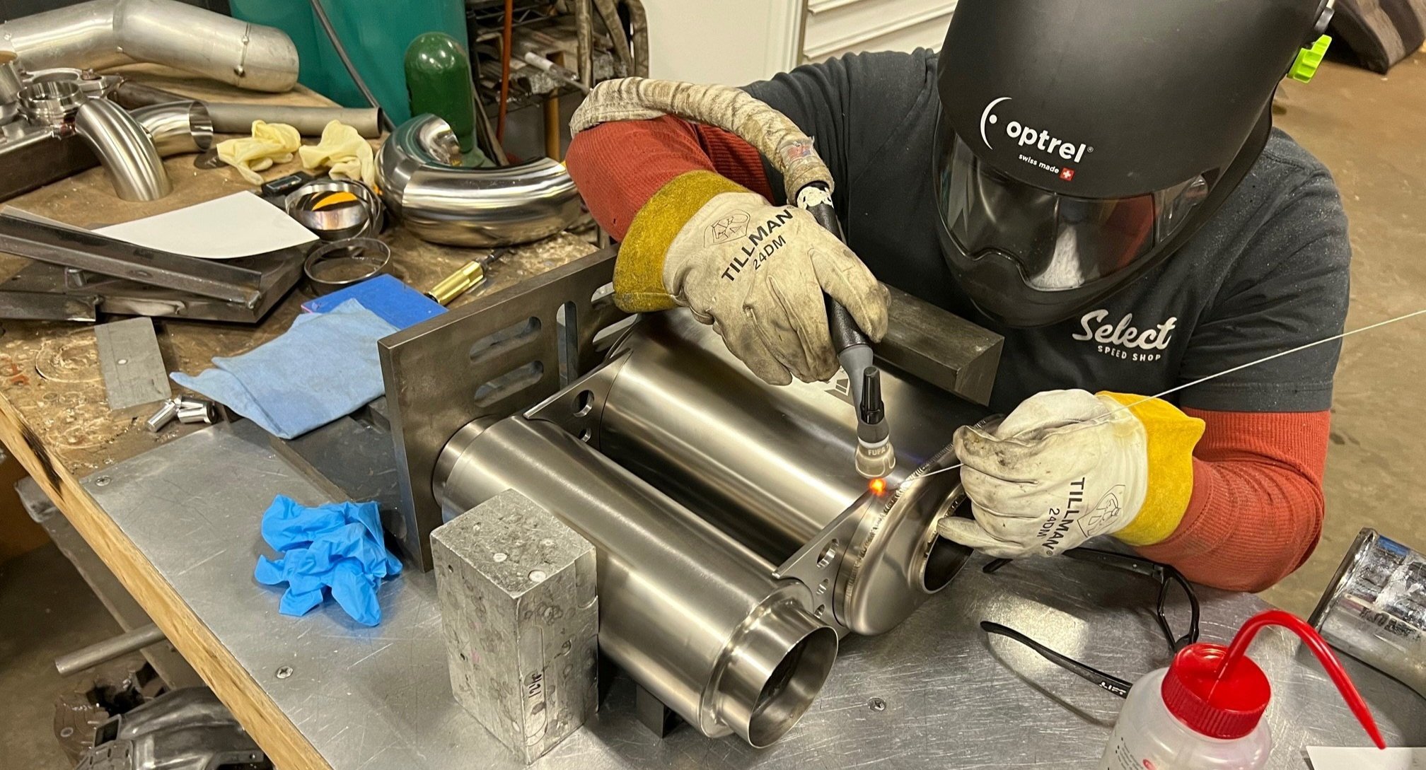
To ensure that everything was aligned the tube ends were welded, the link was installed, the base plate was mounted to the firewall, the clevis plate was bolted to the clevis and a small amount of compression preload we applied (i.e., the link pushing the clevis plate into the base plate). A couple of clamps were added and the bracket was heavily tacked. After the bracket cooled, welding was completed on the bench.

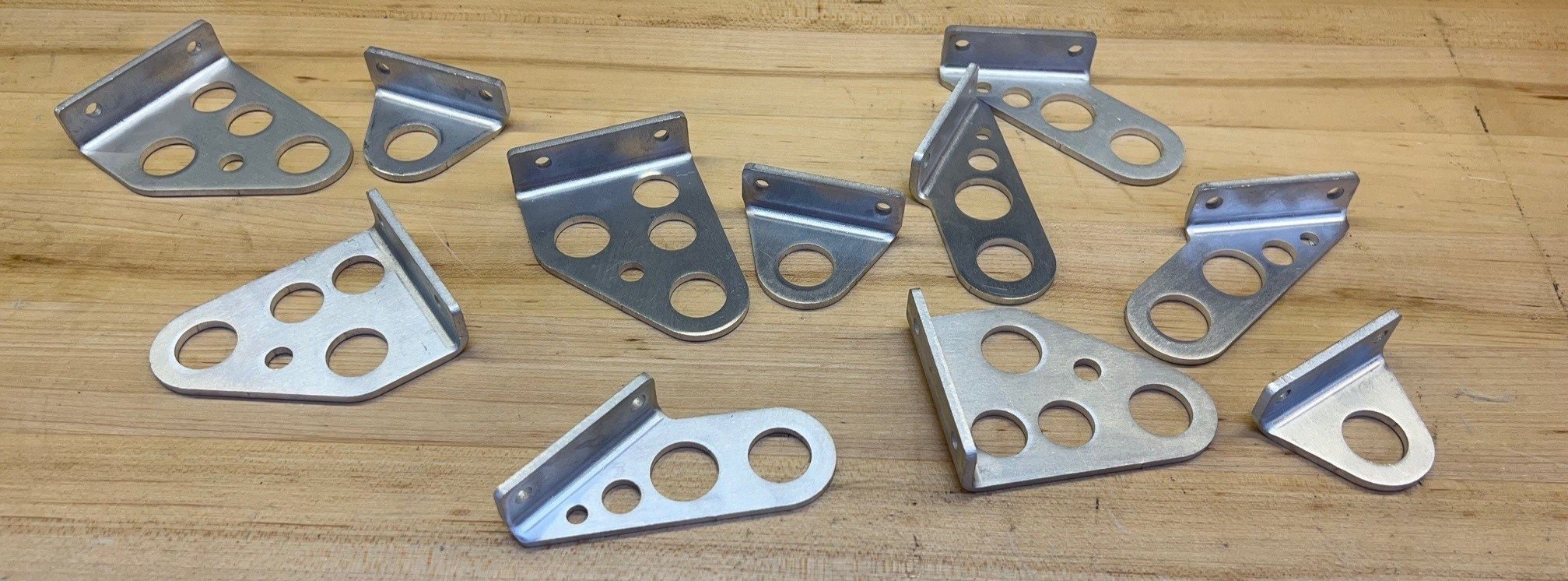
Stock leg (left) and modified leg (right). 3/4”-16 RHT slot clevis at the top and matching LHT tube ends and floating grade 8 threaded rod at the bottom.

Wow it’s easy to install/deinstall the rear hoop legs. Nothing dropped, no profanity and to top it off I can set the perfect amount of preload. I’m very happy with this modification.

The next step is to finish the left side.

SendCutSend's Bending Services

I’ve used SendCutSend to laser cut many aluminum, 4130 and titanium parts, but I had never used their bending services. Last week I needed to fabricate a bunch of brackets with precise bends, so I decided to give their service a whirl. I was specifically curious how close the actual parts would be to the 3D-printed prototypes.

The bent brackets (green) will support the heatshield (mauve) and attach to the transaxle via the vibration/heat isolators (purple). The rear bracket will also provide support for the X-pipe. There will be at least 6 and potentially as many as 8 different brackets.

I didn’t use SendCutSend’s online bend calculator because I had already designed the brackets using Solidwork’s sheet metal features which automatically takes into account bend allowances. I highly recommend that you use a CAD-based sheet metal tool to design these types of parts because; (1) it makes things infinitely easier to design the part, (2) you can 3D print prototypes and (3) you can create assemblies like the one pictured above to tweak and validate the design.

SendCutSend’s bending guidelines are helpful and easy to understand. The only thing that I needed to change in Solidworks was to set the K Factor and Bend Radius values to what was spec’d on SendCutSend’s website for the material being bent. This changed the bend profile a bit, so I reprinted the prototype brackets. I then exported the flat patterns to DXF files ensuring that the bend lines were included, uploaded the files to SendCutSend and indicated if the bend lines should be oriented up or down. Wow, that was easy.

SendCutSend laser cut and bent these parts from 1/8” 5052 aluminum. While these brackets only have a simple 90-degree bend, SendCutSend supports significantly more complex bends.

Left/right mirrored versions of the same bracket to compare the 3-D printed prototype to the final bent aluminum part. The match is pretty much perfect as far as I can tell.

In low volume, each bend costs $2 with a $9 bend minimum. For example, one bend will cost you $9, but 5 bends will only cost $10 (I think I got that right, but their quoting is transparent and instantly updates). The good news, is that the minimum applies to the whole order and not a specific part. This is an excellent deal if you think about it. In my neck of the woods a fabricator costs $120/hour which equates to $2/minute. It would take an expert with a non-CNC brake longer than that to mark the part, align it and bend it. I could have easily bent these parts in my brake for free, but it would have been impossible to be as precise. In addition, while my brake has fingers, they all have the same profile which is fairly pointed. SendCutSend has specific dies for every thickness of material that they bend which, as proven above, means that I can almost perfectly model bent parts (as least simple ones).

The only downside is that bending will add a couple of days to the typical one-week delivery time.

I have some more complicated parts that require bending and it looks like SendCutSend will handle any of the parts that I will draw in CAD.

Power Brakes - Part 2

In a previous post, I discussed my plan to implement power brakes with a GEN1 Bosch iBooster, I fabricated a bracket to mount it and I machined the pedal box.

The next step was to connect the brake pedal to the iBooster. Since the iBooster has only one input rod the front/rear brake bias will be adjusted via a hydraulic proportioning valve rather than the balance bar that came with the pedal box. I removed the balance bar and was surprised at how small the mechanism was. I would have thought that more contact area would be required, especially given that the pedals are cast aluminum, but the Tilton guys know what they’re doing.

Stock balance bar (left) and custom balance bar replacement (right). Note that the bolt heads are drilled for a safety wire.

I wanted to replace the balance bar with something that was unquestionably strong and had a precision fit. I’m pretty sure that 6061 aluminum would have been strong enough, but when dealing with brakes it makes sense to be conservative. I considered using steel, but it’s heavy and it would rust inside the pedal. McMaster offers tight-tolerance (0.0005" to 0.0000") high-strength 7075 aluminum rod. While it doesn’t like to be bent, it’s incredibly strong which is why it’s used in aerospace for structural applications.

Using the lathe, I machined the rod a few thousands wider than the pedal and drilled and tapped 5/16"-24 holes in the ends. While there should be minimal lateral forces, I laser cut retention discs from 0.060" stainless steel to restrict lateral movement. The 5/16"-24 rod ends are held in place by grade 8 washers and hex bolts with drilled heads so that they can be safety wired.

I removed the clevis from the iBooster’s input rod to keep everything compact and to reduce the number of connections that might introduce play into the braking motion. Note that some OEMs utilize an extension rather than a clevis. I then fabricated an adapter from 1/2” x 3/4” 4140 bar, 1/2” OD 0.058” wall 4130 tube and 5/16”-24 4130 tube ends. The center was tapped for the input shaft’s M10 x 1.5 mm thread and I bored holes 80% of the way into bar to receive the tubes. It would have been less work to fillet weld the tubes to the bar, but the bored holes help jig the tubes during welding and they result in a stronger assembly.

Parts ready for welding; adapter bar (left), tubes (middle) and tube ends (right)

The adapter connects the two rod ends bolted to the brake pedal insert to the iBooster’s input rod. The tube ends haven’t been tacked yet and the input rod’s bellow has been temporarily removed.

While the base of the tubes were jigged, I didn’t jig the ends of tubes and one of them warped inwards during welding, so I’ll need to remake this part. I’m worried about having enough master cylinder travel so the iBooster is spaced 1/4” off of the bracket, the tubes were left long and the tube ends are only lightly tacked. Without any fluid in the system, I pressed the brake pedal until it bound on the adapter bar. This resulted in about 5-1/4” pedal travel, as measured from the middle of the pedal, and about 15/16” of master cylinder travel. From what I can tell, the master cylinder has a 1” bore which would mean that I shouldn’t need much travel. However, I think that the single input rod drives two internal master cylinders (the reservoir has two feeds) and I have no idea how that changes things.

The master cylinder has two M12 x 1.0 mm pressure ports, so I purchased a set. D’oh! The seat is deeply recessed and the hex nut bottomed before the flare seated. No one seems to spec how far the threads extend which required looking at a lot of pictures to find one that would work. Fortunately, the second time was the charm and K-Motor Performance had the solution.

M12 x 1.0 mm to -3 AN fittings; note how much longer the M12 threads (the ones pointing down) are on the right fitting offered by K-Motor Performance

There are lot of unknowns regarding master cylinder travel, how the internal master cylinders are sized, the size of caliper pistons (although I could figure that one out). So, the next step is to plumb the iBooster into the car and see what happens. I’ll measure the pressure at the front and rear calipers with a gauge both with and without the iBooster powered up. That should give me a good idea if I have enough pedal travel, what the amount of boost is and if the master cylinder size provides enough volume for my brakes. I have the Brembo GT upgrade, so I’ll need more volume than the stock brakes.

Power Brakes: Part 1

Several owners that I know with finished SL-Cs lament not having power brakes. I asked Allan, who’s built 28 SL-Cs and 5 GT-Rs, and he indicated that brake pedal effort is the number one complaint by far. I don’t have power brakes in my cobra, but the SL-C is heavier, more powerful and with active aero, it’s capable of quicker deceleration. I’m also not a spring chicken and my right knee bothers me more than it used to.

Power brakes typically use engine vacuum to operate on a diaphragm. Whomever figured this out back in 1927 was brilliant because vacuum is a side effect of a combustion engine so it’s a “free” power source. Vaccuum-based power brakes have been implemented by at least one SL-C builder (Joel), but the diaphragm takes up a lot of room and it won’t fit inside of the footbox. If I were to place it outside of the footbox, as Joel did, it would collide with my radiator outlet duct.

Electric vehicles (EVs) have power brakes, but no combustion engine and therefore no engine-generated vacuum. So, what do they do? Early model S Tesla’s used an electric pump to create a vacuum which was a poor solution because the pump ran constantly which was a drain on the battery. Apparently, several years prior the Tesla hack, the Toyota Forerunner employed an electromechanical brake booster, so Elon wasn’t the innovator in this area.

Fortunately, Bosch manufacturers an electromechanical brake booster which is used by many OEM EVs. In addition to removing the dependance on a vacuum, pedal feel can be adjusted through the configuration of braking characteristic curves. This allows the iBooster to be used across models or support different driving modes within a model (see diagram below). While having different braking modes is interesting, just being able to finetune one mode is extremely useful. The only way to change brake pressure on a SL-C is to swap the front and/or rear master cylinders which is both messy and time consuming. The SL-C’s tight footbox makes this a bit of a nightmare and master cylinder increments are at least 1/16,” so changes aren’t granular. While I haven’t found anyone that’s hacked the CAN bus to change the default brake characteristic curve, other builders have figured out the CAN bus messages implement brake by wire and determine the master cylinder’s position.

There are two primary versions of the iBooster; GEN1 and GEN2. TO compare, I purchased a used version of each on eBay. I liked GEN1 vs. GEN2 for the following reasons:

  • It was a bit more compact in the intended orientation.

  • It has a nice cast aluminum body with several machined surfaces whereas the GEN2 is all stamped steel and seems shoddy by comparison. I’m sure this is my perception rather than an issue with the design. GEN1 feels like the engineers were focused on a high-quality innovative solution and GEN2 was engineered to hit a price point.

  • There is more information on how to hack the CAN bus on GEN1 than GEN2 which makes sense because it’s been out longer. While CAN bus integration isn’t required, it’s something that I’d like to do in the future.

GEN1 (left) and GEN2 (right); the reservoirs vary widely amongst the OEMs

GEN1 iBooster donor cars include;

  • Audi A3 e-Tron

  • Chevrolet Bolt

  • Chevrolet Malibu

  • Honda CR-V (MY 2018, 2019)

  • Jaguar i-Pace (MY 2019, 2020)

  • Porsche Panamera (MY 2017+)

  • Tesla Model S (MY 2015+ with autopilot)

  • Tesla Model X (MY 2015+)

  • Volkswagen Passat hybrid

  • Volkswagen e-Golf and Volkswagen e-UP

I didn’t want to pay the Tesla tax, so I purchased a GEN1 from a Honda. The mounting flange, master cylinder and reservoir are easily removed and appear to vary amongst different OEMs. The master cylinder has pressure ports cast on both sides with only one side being drilled and tapped. I assume this is accommodate fitment for different cars including left vs. right-hand-hand-drive within a model. In addition, I read somewhere that the Honda version was machined differently to accommodate a different master cylinder.

Enterprising builders have utilized the iBooster in homebuilt EVs, restomods, hotrods, etc. They figured out that iBooster can be operated in a fail-safe mode without any CAN bus connections. To operate in the fail-safe mode, the 26-pin ECU connector only needs four wires (two constant +12v power, ground and ignition) and four wires that connect to the position senser to the ECU. There are multiple wiring kits available (e.g., EVcreate, Tulay’s Wire Works, SGH Innovations) or you could cut it out of an OEM harness.

Given that all of this has already been figured out, installing an iBooster is straightforward. However, the SL-C presents several challenges:

  • The footbox and nose are tight.

  • The pedal box sits on the floor which means that iBooster needs to be properly tilted to align it with the brake pedal.

  • The pedal box uses a balance bar to connect to the front and rear master cylinders and the iBooster has only one input rod.

I considered mounting the iBooster in the nose, but the extended footbox projects too far for it to be mounted longitudinally (a standard footbox would probably result in a simple install). I also considered using a bellcrank and mounting it transversally, but that seemed like a hack. In the end, I designed a bracket that locates the iBooster as low and close to the pedal box as possible inside the footbox. I read somewhere that pedal force should be as concentric as possible with a master cylinder’s input rod and that it must not diverge more than 3 degrees. My bracket tilts the iBooster’s nose down 15.75 degrees from the vertical to perfectly align, as far as I can discern, the center of the balance bar with the iBooster’s input rod. Any changes to the iBooster’s location would necessitate the angle.

Laser cut 1/8” 4130. There are 36 tabs and slots. All of the corners are relived and there is only five thousands clearance between the slot edges and the tab edges (i.e., the tabs are 0.125” thick and the slot is 0.135” wide). The only edge that I filed was the bottom of the angled plate. This was by design to keep the weld gap small. If I had CNC machined the plate that wouldn’t have been required, but laser cutting is significantly less expensive. I assembled the four sides, wiggled them into the bottom plate, added some clamps and welded. As intended, the part pretty much self jigged which ensured that the booster is at the correct angle.

Front view, bracket welded and primed with a rattle can

Rear view. Note the two nuts that are welded to the bottom rear edge. The left vertical plate is larger than the right to mount the GM accelerator which most SL-Cs utalize.

Many builders add a plate under the pedal box to prevent the floor from deflecting. If you look carefully at the pedal box, you realize that it was carefully optimized, likely with finite element analysis (FEA), to reduce weight. There are only five relatively small contact patches with the aluminum floor (see diagram below). The four mounting holes are centered around the brake pedal. Note that the rear bosses are slightly larger than the front bosses and that there is only a small rectangular contact patch in the upper left to counteract the force applied by the clutch pedal. In addition, the mounting bolts are only 2.225” apart in the direction of the brake pedal force (i.e., front to back). For these reasons, the bracket extends under the pedal box and provides two additional mounting points at the rear of the bracket. When combined with the large truss supporting the iBooster, the bracket significantly stiffens the floor while only raising the pedal box by 1/8.”

Mounting holes and floor contact patches

The next step was to modify the pedal box to convert the dual cylinder configuration to a single input rod (I think the iBooster has two master cylinders inside). I used the mill to remove the top of the front and rear master cylinder brackets. This in no way reduces the strength or integrity of the pedal box base. The cast aluminum is high-quality and there wasn’t even a hint of an air pocket. It felt like I was machining billet.

The red cap points to the area where the upper portion of the brake master cylinder supports and studs were machined off. Note that the clutch mount in the background is intact. The lower brake cylinder studs are bolted to the bracket.

The bracket mounts to the front and rear brake cylinder lower studs. This allows the entire assembly to be installed and removed as a single assembly. The bracket clears the ECU and clutch master cylinder by about 1/16.”

The next steps are to:

  • Replace the balance bar with a custom adapter. I’ll know at that point if I left enough space between the pedal box and iBooster to achieve full master cylinder travel.

  • Temporarily wire the ECU and the position sensor.

  • Temporarily plumb the master cylinder to pressure gauages.

  • Determine if the master cylinder has enough volume to support the Brembo GT calipers.

  • Adapt the reservoir inlets to AN fittings.

If anyone has information on iBooster master cylinder volumes or how to set the brake characteristic curves, I’d love to hear about it.


Titanium Cat-Back Exhaust Tacked

The rear is starting to look pretty wicked. Everything after the catalytic converts is 3.5” titanium. The muffler assemblies are fully welded and the rest is tacked. The first step was to connect the catalytic converters to the mufflers via titanium pie cuts. A titanium flex bellow was used to absorb linear growth caused by thermal expansion and to help decouple vibrations.

The flex bellow is visible on the upper tube

Once the upper tube was completed, the muffler outlets were connected to the X-pipe. The challenge was to determine the exact location of the X-pipe and to keep it there during fabrication. The solution was a piece of 1/4” plywood. The leading edge was clamped to the underside of the billet chassis piece that crosses under the transaxle and two vertical supports were fabricated from right-angle aluminum to affix the trailing edge to bosses on the transaxle. Slots were milled in the supports to enable granular adjustments. This provided a stable platform to locate the X-pipe and enabled the X-pipe to be precisely tilted (the tips will be tilted upwards). This worked much better than a floor stand because everything moved when the car was raised/lowered via the lift and there was no chance of knocking over the stand or dumping everything on the floor.

Plywood platform to support the X-pipe while fabricating the connecting tubes. Plumb bobs, squares and digital angle finders were used to get everything symmetrical.

Merge collector (left), bell housing (top middle) and four primaries joined by a flange crossing under the oil pan (bottom middle)

Merge collector (left) flowing into a transition cone (middle) leading to a catalytic converter after which pie cuts flow into the bellow

The X-pipe is connected to the muffler outlets. A mock exhaust tip on the left side.

The final step was to connect the mufflers to the X-pipe which required a fair number of pie cuts of different centerline radiuses (CLRs) and slip fittings to enable the muffler assemblies to be removed/installed.

The cat-back system required 82 pie cuts, 6 mandrel bends and 4 straight sections. When V-bands, bellows, slip fittings and transition cones are taken into account there are 113 welds with a 3.5” diameter. That results in a whopping 1,242” or 103.5 feet of welding!

The next steps are to integrate the cutouts, finish weld everything, add hangers with vibration isolators to the X-pipe and fabricate a heat shield between the X-pipe and transaxle.

Wing ECU

I finally got around to mounting the ECU for the active wing. It has four feet with mounting holes so that should be simple, right? Nope…

There are no instructions regarding mounting the ECU and when I went to install it, I realized that it had a cooling fan. I called Aeromotions and they confirmed that the ECU will not tolerate any moisture. Front-engine cars mount the ECU in the trunk and the Ferraris mount it under the passenger seat, neither of which is feasible in the SL-C.

The ECU must be in one of two orientations for the accelerometers to work and you need access to the control panel. The only location was under the dash where a normal car would have a glove box. I already hate doing anything under the dash and that’s only going to get worst when the interior is finished which made it important that the control panel was easily accessible. I considered hinging the ECU, but there wasn’t enough space for it to pivot in place. The solution was a dual motion bracket; (1) slide down to clear the bottom of the dashboard and (2) pivot to provide access to the control panel.

Laser-cut 0.060” stainless steel and stainless-steel piano hinge. I subsequentially added slots to the glide plate to provide access to the guide rail mounting screws.

As mentioned above I really don’t like doing anything under the dash, so I looked for a quarter turn fastener that didn’t require a tool and could be easily released without seeing the fastener. I found these AeroLoc fasteners with bail handles at Pegasus Auto Racing. Unlike winged Dzus fasteners, the bail handle can be flipped flat (and they stay that way even if the fastener is inverted). I can reach under the dash, flip the handle down and twist it a quarter turn without needing to see anything.

To implement the sliding motion, I considered machining slots on the glide plate and fabricating flanged bushings on the lathe. However, I didn’t want things rattling so I used low-profile sleeve bearing carriages and guide rails from McMaster. The carriages apply a small amount of pretension to the rails which provides smooth motion and prevents rattling.

Bracket installed on chassis and locked in place with AeroLoc fasteners. I need to trim the tops of the guide rails a bit.

ECU installed

ECU slid down and rotated to provide access to the control panel. The guide rails are clearly visible.

Well, that was several orders of magnitude more work than what I expected, but the results were worth it.

Coil Packs

I upgraded the OEM coil packs with RaceGrade IGN1A coil packs. They contain an inductive ‘smart coil’ capable of producing extremely high spark energy (103mJ+) and are suited to anything from moderately-powered-endurance applications through 3,000+ horsepower blown-alcohol motors. Since no external igniter or CDI is required and high-quality connectors must be used due to the immense energy of this coil, a custom wiring harness is required.

RaceGrade coil packs on top and OEM coil packs on bottom. The RaceGrade coil packs are larger and have integrated heat sinks, upgraded connectors and steel inserts in the mounting holes.

I appreciate the simplicity and efficiency of mounting the coil packs to the valve covers, but I abhor the aesthetics. So, I spent a fair amount of time figuring out a location where they would be completely hidden, easy to service and out of the way. The top of the upper 2”x2” chassis tube under the body seemed a good location because, with the addition of a closeout panel, they can be completely hidden. I mocked several brackets, but they extended a little past the body which would interfere with the closeout panel. It then occurred to me that I could tweak the design to extend the bracket a little past the vertical 2”x2”, problem solved.

Six parts laser cut from 0.100” stainless steel, 10 aluminum spacers spanning three different lengths, and two 1/4”-20 grade 8 screws.

Bracket fully welded; the tabs and slots made fixturing easy, but I did fabricate two temporary aluminum spacers to replace the coil packs which allow me to tighten down the bolts to keep the ears from warping.

The bracket mounts with three 1/4”-20 screws that mount through the 2”x2” chassis rail. It’s easy to install/remove, very robust and allows the body to removed.

Fuel Cell: Part 1

The fuel tank is well protected from an impact. However, it’s possible that a crack forms on one of the welds due to a collision or a from vibration fatigue. For this reason, it has always bothered me that the fuel tank is essentially in the cockpit. I considered a fuel cell, but they need to be replaced every five years and there are only two ways to remove one, both of which are onerous in street car with a finished interior:

  1. via the cockpit: If you have a tub, which I do, you need to remove the body, windshield, cage, interior, tub and fuel tank cover panel. That’s a lot of work, but the real issue is that the body requires a massive amount of attention to seal the footbox, side pods and firewall and all of that needs to be torn out and replaced. UGH!

  2. via the engine bay: This requires the engine, oil reservoir, surge tank, coolant swirl tank, firewall, etc. to be pulled which isn’t that bad in a race car which is specifically designed to efficiently pull the engine, but a lot of work for a painted street car. However, the mounting brackets that I welded to the top of the fuel tank would prevent it from sliding through the chassis rails and I would have needed to carefully mount the tank so that I didn’t need access to the interior to reach any bolts. Lastly, I had already installed a permanent fire wall between the tank and engine compartment. So, this approach wasn’t a viable option for me.

Then I had an idea which is always dangerous. I could cut a big hole in the bottom of the stock fuel tank and the monocoque’s floor so that I could install a bladder from the bottom of the car. This would allow me to address several things that I don’t like about the fuel tank:

  • E85 doesn’t like raw aluminum.

  • The 2” fill tube doesn’t have a flapper valve. If you roll the car, you’re relying on the flex tube and gas cap to contain the fuel, both of which are attached to the fiberglass body and could be easily torn off. If that were to happen, the opening is 28x larger than the -6 vent that everyone puts a roll over valve on.

  • The rollover valve should be located inside the fuel tank. Otherwise, it needs to be located in the engine compartment which increases the number of connections, takes up space and creates the potential for a leak if the line between the tank and the valve is damaged in a collision.

  • Significant modification is required to implement a fuel pickup system (e.g., HydraMat, corner pickups, sump with trap door, etc.).

  • If you have a tub, you need to tear the car apart (i.e., via one of two options listed above) to service the fuel-level sensor and I’m aware of many builders who have had them fail.

  • Doesn’t support an internal lift pump without modifications.

  • No foam to prevent a flame front from forming or reduce sloshing.

  • The NPT bungs should be ORBs.

The first step was to remove the “finished” low-pressure fuel system and fuel tank. In a previous post, I used dry ice to remove all of the sound deadener from the tank. I then cut the largest hole possible between the 2” x 2” welded to the monocoque’s floor.

Access hole cut into floor. The large size makes it as easy as possible to install the bladder.

After reinstalling the tank, I marked the location of the 2” x 2” chassis tubes on the bottom of the tank. I removed the tank, flipped it upside down on the bench, marked an access hole that left a small flange around the 2” x 2”s and the front and back of the tank, drilled the four corners with a 5/8” hole saw and cut the hole with a 4-1/2” cutoff wheel. There are two baffles in the tank, each with two weld beads on three different edges, which meant that I had to break a total six weld beads per baffle. I accomplished this by cutting the baffle into thirds so that each piece isolated the two beads on each edge. After which I wacked each piece with a hammer to rock it back and forth until the weld beads cracked. The baffle in the picture above was relatively easy to remove because it was in the hole that I had cut. The other baffle was a more difficult to remove because it was tucked inside the tank.

Rough opening cut, baffles still in place

I then clamped a piece of steel to act as a limiter while I ground the edge with a 4” 40-grit sanding disk. As you can see in the picture below, the right side is straight and smooth whereas the top and bottom edges haven’t been finished yet. Because I don’t trust my cutting skills, I left more material than needed which required a LOT of grinding.

Right edge finished, top and bottom edges will be finished next

I then removed the weld bungs for the fuel outlet, fuel return and vent because they protrude inside the tank and would hit the bladder. The easiest way to accomplish that was with a hole saw. Since the existing hole was much larger than the pilot bit, I fabricated drill guides by chucking up NPT plugs in the lathe and center drilling them. I had a similar issue when enlarging the fuel fill hole. In that case, I tack welded a temporary disk to act as a drill guide for the pilot bit (see picture below).

Temporary disk tack welded to act as a guide for the hole saw’s pilot bit

Once that was done, I removed the shift cable tube (I’m using paddle shifters) and the fuel-level sender flange after which I smoothed and deburred every edge in the tank. When I was done the shop was a mess and I had exerted significantly more effort than I had originally anticipated. If I had paid someone to do the work, it would have been much less expensive to have had a custom shell fabricated out of thinner aluminum. I took this approach because I had already mounted the tank and made perfectly aligned cutouts in the in the firewall not to mention that my labor is free.

I drew the tank with the desired fitting locations in CAD and worked with Hill at Agile Automotive to help me spec and order a fuel bladder that solves all of the aforementioned issues with the tank.

All connections are easily accessible via the access panel cut into the floor (the above picture was taken through that opening); fuel outlet (bottom left), motorsport electrical connector for the lift pump and fuel level gauge (middle), and fuel return (top right).

The foam, lift pump and fuel pickup rig is installed/removed through the oval access panel. This enables the fuel bladder to collapsed so that it can be installed/removed through the holes in the monocoque floor and the bottom of fuel tank.

The fuel fill has a flapper value to prevent a leak if the car is rolled. I need to modify my firewall to accomidate the flange and allow the retention clips to be rotated when installing or removing the bladder.

Stock fuel level sender flange has been removed. The new fuel level sender can be easily serviced when the bladder is removed.

The hose end that connects to the roll over valve doesn’t clear the fuel tank cover panel because they weren’t able to locate it directly against the back of the bladder because they needed to provide room for the internal flange. This moves the location forward into the sloped fuel cover panel. I’m on my third iteration of a solution… I’ll figure it out eventually.

The next steps are:

  • solve the roll over valve clearance issue

  • clean up the cut out in the floor

  • fabricate a support shelf for the bottom of the bladder

  • fabricate a close out panel for the bottom of the car

  • modify the firewall to accommodate the fuel fill flange

  • validate that the bladder can be removed and installed using only the two access panels

Left Muffler Assembly Mounted

In a previous post the muffler assemblies were tacked together. The next step was to extend the tail subframe to support the muffler assemblies, bumper and diffuser (the latter two are still in the conceptual phase). The main subframe is fabricated from 1” OD 4130 and the new extensions are made from 1/2” OD 4130 which is difficult to bend with a manual tube bender. To facilitate prototyping, I purchased a coil of 1/2” aluminum tubing. It’s inexpensive, easy to straighten with the right tool, easy to cut, easy to bend and simple to recycle when done. Once the subframe extension was prototyped in aluminum it was replicated in 1/2” 4130 and welded to the 1” subframe.

Muffler assembly resting on 3D-printed supports sitting on top of a motorcycle jack

The next step was to figure out exactly where the mufflers would be positioned. I 3D printed two brackets to support the bottom of the muffler assembly and placed them on top of a motorcycle lift sitting on a cart with lockable wheels. Which, combined with the car lift, made it easy to position the muffler assembly exactly where we wanted it and quickly move it to tack something without worrying about dropping the assembly on the floor.

Vibration isolator (top left), 0.187” titanium tab (top middle), 1/8” 4130 tabs (bottom left), 3D-printed muffler supports (right)

I opted to hang each muffler assembly via three vibration isolators. To accomplish that, I designed and laser cut three different 4130 tabs to weld to the 1/2” sub frame and three copies of a titanium tab for the muffler assembly. Note that in the pictures below many areas were just tack welded when the pictures were taken.

The next step is to replicate everything on the right side and finish weld all of the seams.

Scavange Filter

The Daily Engineering dry sump pan is a piece of art. Unlike most other dry sump pans that have a multitude of scavenge lines projecting from the sides, Daily CNCs those pathways into the pan which provides a much cleaner installation. However, this results in a single large scavenge line which requires a massive scavenge filter rather than a small filter or screen on each of the protruding lines. Daily recommends a -16 400 Series filter from Peterson Fluid Systems. It’s 2-1/2” in diameter, 9-3/4” long and the -16 hose and hose ends are huge with a large bend radius. All of this makes it difficult to package the filter between the engine and the oil reservoir.

The top and bottom halves of the oil reservoir can be independently clocked which is helpful when routing hoses. However, no matter what I tried, I was unable to get any flexible hose between the filter and the tank and I settled on a solution that utilized a 45-degree union fitting that attaches the filter directly to the reservoir. The issue with that approach is that there is no flex hose to isolate the filter from the reservoir and they will vibrate at different frequencies which will eventually cause the weld on the bung in the reservoir to crack.

Temporary “angle finding” jig

To solve that problem, I needed to fabricate a bracket to dampen filter vibrations. The challenge was that the filter and the 2”x 2” chassis tube were pointed in different directions with a compound angle between them. I purchased a panel-mount billet bracket from Peterson, but measurements and angle finding attempts between it and the chassis provided futile. I then hacked together the above “angle finding” jig with two pieces of scrap right-angle aluminum and a vibration-dampening sandwich mount. Since there is only one screw per connection it provides four axes with 360-degrees of rotation each of which was orthogonal to the adjacent axes.

Within a matter of seconds, I was able to get it perfectly aligned. Wow, that was easy! I tightened the screws to preserve the orientation and removed the bracket which made it easy to measure the angles on the bench. This allowed me to design a bracket. The single screw per connection was critical to the angle finder, but antithetical to the bracket’s purpose so it utilizes two screws per connection to prevent rotation.

The bracket was laser cut from 1/8” stainless steel because welding small aluminum parts isn’t fun and the parts were well under the $29 order minimum. I added a couple of other parts and was still under the minimum.

3D-printed prototype bracket (left), welded stainless steel bracket (middle) and billet Peterson bracket (right)

Bracket assembled and ready for installation

Filter and bracket installed

The next step is to run the -16 hose to the pump and weld a couple of gussets to the weld bung just to be safe.

Mufflers Tacked

The cat-back exhaust system will be made from 3-1/2” titanium tube. Each side has a 4.6” OD round muffler that flows into two 90° tight radius elbows and a 6” x 9” oval muffler. I designed brackets to connect the mufflers and had SendCutSend laser cut them from 0.187" Grade 5 titanium. They have good pricing, but titanium isn’t cheap and four of them cost $310.72. As is typical, I 3D printed a pair to ensure fitment before pressing the order button.

3D-printed tack-welding supports and titanium brackets

Mufflers and brackets being tacked. Note that the 3D-printed supports under the round muffler (center bottom of picture) perfectly aligns the mufflers and prevents the round muffler from rolling.

Excellent muffler/bracket fit

Once the brackets were tacked the elbows were tacked

Left-side mufflers manually held in place

The next step is to fabricate a frame from 1/2” OD 4130 tube to support the mufflers and the bumper. Once that’s done there will be a lot of pie cuts to connect to the catalytic converter and the x-pipe.

Actuated Sway Bars

In a previous post I installed the sway bars which I had purchased from Agile Automotive. They’re the same as the ones in their endurance SL-Cs which utilize cockpit-adjustable Genesis blades. Each blade rotates within a barrel on a cage bearing and a needle bearing. When the blade is horizontal it provides minimum stiffness. As it rotates stiffness increases until it reaches the vertical position, at which point it provides maximum stiffness.

Genesis cockpit-adjustable blades; the horizontal orientation (left) provides minimum stiffness and the vertical orientation (right) provides maximum stiffness. Since the lower control arm moves straight up and down it’s intuitive that the horizontal orientation’s signifcantly smaller cross-sectional area is easier to bend.

Typically, a blade is used on one side of the sway bar and a welded arm is fabricated for the other side. I opted for a symmetrical approach that utilizes two blades in which one blade rotates and the other is stationary. I took this approach for the following reasons:

  • If the bearings fail on the rotating side, I can simply flip the sway bar and invert the configuration.

  • The stationary blade can be rotated to any position to shift the adjustment range of the rotating blade up or down. Although this has to be done while the car is stopped, you simply loosen one screw (see picture below), rotate the blade to the desired position and tighten the screw.

  • One blade is soft and the other is medium which enables me to swap them between the rotating and stationary sides of the sway bar to obtain different cockpit-adjustable ranges.

  • It looks cool… maybe I should move this to the top of the list LOL

Loosening this socket-head cap screw allows the stationary blade to be rotated to any position. This will shift the adjustment range of the rotating blade up or down

The front and rear blades are typically controlled via 10-32 push-pull cables connected to levers in the cockpit. I decided to use linear actuators for the following reasons:

Genesis cockpit-adjustable sway bar levers

  • The levers only provide five equally-spaced positions whereas the actuators provide infinite adjustability.

  • The levers are appropriate for a race car, but they crowd the cockpit of street car.

  • It’s easier to route electric wires than push-pull cables.

  • When used with position feedback, presets can be implemented (e.g., Wet, Sport, Track, Race)

It took me a long time to find the right linear actuator. I wanted a tubular form factor for fitment reasons, the correct stroke, at least an IP67 rating (i.e., waterproof for short-term submersion), excess load capacity, and position feedback. I found one that checked all of the boxes except the feedback. It had an optical encoder option, but I wanted absolute rather than incremental position feedback. To solve that problem, I purchased a motorsport-quality linear potentiometer.

The best location to mount the bracket was the nose subframe. I designed a 3D-printed bracket, but it didn’t clamp the tube as tightly as I wanted. The solution was a hybrid composed of two-piece stainless steel clamping shaft collars, 1/8” stainless plate and 3D-printed parts. It’s robust and light.

Stainless steel and 3D-printed parts for the front and rear brackets for the front sway bar actuator

All parts for the front sway bar actuator bracket are welded; rear bracket (left), front bracket (top) and actuator tip bracket (right)

Ready to install; 10-32 threaded rod (left), linear potentiometer (red), linear actuator (black)

The video below provides a quick overview and demonstrates the actuator rotating the blade. Ignore the hex nuts, they’ll be replaced with nylocs at a later time.

I purchased milspec trim switches which will be mounted to the steering wheel as shown below. Upward pressure increases stiffness and downward pressure decreases stiffness. The switches will be connected to MoTeC inputs and the actuators will be driven via H-bridges so current through the switches will be nominal. The mode switch in the lower right will move the sway bars to configurable presets in addition applying a bunch of other settings (e.g., engine tune, gear-shift tune, percent slip, etc.).

Mock steering wheel. The top trim switch is the front sway bar and the one under it is the rear sway bar.

Heat-Set Inserts

There are four common ways to add female threads to a 3D-printed part:

  • Print them: This is only practical for larger threads and, depending on the print geometry, the support material may need to be removed with a tap if it’s not water soluble.

  • Tap the printed hole: This is only practical for small thread pitches unless you’re printing with a 100% fill which significantly increases cost, print time and weight. The issue is that most slicers only allow you to specify a global value for the following parameters: number of floor/roof layers, number of wall layers, and fill density percentage. Thee default settings for my printer are four layers for floors and ceilings, two layers for the walls (they can have different values) and 37% fill density and once you’re past the wall/floor/ceiling layers, you’re into the honeycomb. There might a slicer that enables you to increase the amount of structure around specific internal features (i.e., a hole), but I’m not aware of it.

  • Embed a nut: Depending on the geometry, printing may need to paused to insert the nut.

  • Install a threaded heat-set insert: Depending on the geometry, printing may need to paused to install the insert.

I haven’t found a situation on the car where printing the threads was feasible, so I will compare the other methods vs. heat-set inserts.

Threaded Heat-Set Insert vs. Tapped Hole

Pros:

  • Up to 3x stronger

  • Unlimited assembly/disassembly

  • Eliminates creep

  • Stronger resistance to torque

Cons:

  • Higher cost

  • Requires more space

  • More weight

  • Higher potential to damage part during installation

Several years ago had found an excellent article that published the results of strength testing performed on heat-set threaded inserts vs. tapped holes, but the link is now defunct. That article was the source of the above strength and torque claims.

Threaded Heat-Set Insert vs. Embedded Nut

Pros:

  • Requires less space

  • Lighter

Cons:

  • Less strong

  • Less resistant to torque

  • Potential to damage part during installation

So far none of my parts have been structural, so the lower strength and torque resistance aren’t an issue.

InstallatiNG THREADED HEAT-SET INSERTS

The inserts are available from a variety of places and McMaster has a good selection here. A tapered hole is required to accommodate the insert (the McMaster inserts have 8° taper). The first couple of times I sketched a tapered profile, created a reference-geometry axis and performed a revolved cut of the profile about the axis. I subsequently realized that I could do an extruded cut and specify a Draft — duh, that’s a lot easier, especially since a single extruded cut operation can be applied to an unlimited number of holes.

The inserts are installed by heating them with a soldering iron while gently applying pressure. Although a standard soldering iron tip can be used in some circumstances, I recommend using an installation tip which offers the following advantages:

  • The shoulder on the installation tip sits flat on the top of the insert which makes it much easier to install the insert straight (i.e., orthogonal to the part).

  • It indexes the insert which prevents the soldering iron from slipping off of the insert and melting the plastic on the soldering iron and marring the part’s surface.

  • It heats the insert more evenly which speeds up the process. Specifically, a standard soldering iron tip will only transfer heat via a small contact area at the top of the insert and it will take time for the tip to get hot enough to melt the plastic.

Soldering iron tips; standard (front), #4 (middle) and #10 rear (heat discolors the brass)

The installation tips cost ~$18 at McMaster, but I’m sure that they can be obtained for less elsewhere. Keep in mind that ruined parts can sum to that amount pretty quickly and you don’t need to use the optimal tip because a smaller than ideal version will work better than a standard tip. For example, a #10 installation tip would work fine for a 1/4” insert.

Like the holes, the inserts are tapered so you want to ensure that you orient them properly. Yeah, that’s obvious, but the taper is visually indeterminable and I’ve ruined a couple of parts by not paying attention. The knurling it typically located at the top of the taper, but if you’re not sure you can just mic both ends.

The installation/heating process seems to make it difficult to wind a screw into the insert post installation and some plastic may have been pushed forward into the hole and or into the insert. I found that running a tap through the insert from the soldering iron side solved those issues.

EXAMPLE PARTS

Tube separator for two -8 transaxle oil lines and a -4 air line for the shift servo; two 10-24 threaded heat-set inserts were used on the bottom side

End cap for the side-impact bars. It is tight enough to remain in place without a screw, but I added a heat-set insert to ensure that it wouldn’t move if bumped.

Transaxle Thermostat

I considered mounting the transaxle thermostat to the top of the rear-chassis cross brace, but the routing of the four oil lines was messy. It eventually occurred to me to mount it to the bottom of the cross brace, which solved the routing issues, but increased the complexity of the mounting tabs. Specifically, the tabs are at an awkward angle on the tube’s radius and sunken into the small triangle which made it difficult to take accurate measurements. To solve that problem, I used diagonal cutters to keep shortening the end of a welding rod until it fit. The next challenge was to figure out how to fixture the tabs so that they would be properly spaced, aligned and planar. (i.e., not twisted or bent). Rather than fabricating two separate tabs, I designed a single piece with openings to facilitate cutting the center section out after welding was completed. I then fabricated a temporary plate to enable the fixture to be clamped to the cross brace.

Welding jig; tabs with disposable center section (front) and temporary clamping plate (rear)

Jig clamped to cross brace and ready for welding

The thermostat is a well-engineered unit from Improved Racing. I used a higher-temp version for my engine and in both cases the laser-etched side wasn’t visible. I contacted them and they laser etched the other side of both thermostats at no cost. They have great products (I also have one their oil coolers with integrated shroud, fans and isolation grommets) and excellent customer support. No affiliation, just a happy customer.

Tabs welded, center section removed and thermostat installed

After fabricating the oil lines, I wanted to mount two of them to prevent them from flopping around. The transaxle has a bunch of thoughtfully-designed inspection ports. Their covers seal via an O-ring and feature a tapped M5 boss in the center for mounting stuff. One of the cover plates provided a perfect location to mount a hose separator. The issue was that the hose separator was designed to be freestanding (i.e., the one piece bolts to the other) rather being mounted and it used a screw that was small than M5. The solution was easy. I used an end mill to enlarge the recess on the piece that accommodates the head of the socket head cap screw and I drilled a M5 clearance hole on the tapped piece.

Three of the inspection port covers; note the threaded boss in the center

Hose separators; stock (top) and modified (bottom); yeah the recess isn’t perfectly centered, but that’s what happens when you eyeball things rather than taking the time to do it the right way with an edge finder.

Two of the oil lines held in place via a modified hose separator mounted to an inspection port cover

Side Splitter Support Rods

In a previous post I installed the nose hinges each of which was supported by a splitter support rod manufactured by Fully Torqued Racing (FTR). The next step was to replace the splitter support rods that are located in front of the wheels. The stock locations interfere with the intercoolers’ heat exchangers and while the rods are OK, the clevises are subpar.

I took some measurements and placed an order on FTR’s website. After a month and a half of waiting I attempted to contact them to no avail. Their Facebook site indicates that they’ve left a lot of customers hanging which is shame because they make nice stuff. D’oh! Mismatched splitter support rods would be a disaster. LOL. Fortunately, during the nose hinge project I had swapped the clevises that connect to the nose frame with ones designed for a weld tab, so I had an extra pair of FTR’s sexy pressed-pin clevises left over. All I needed to do was to fabricate the rods.

I purchased 1/2” 6061 rod and cut it to length. I used the lathe to face the ends and drill and tap the holes, all basic lathe operations. The next challenge was to figure out how to machine flats on the rod to accept a 7/16” wrench. It’s trivial to clamp the rod in a vice and machine one flat, but how do I ensure that the second flat is parallel to the first one? I thought about machining something to index the first flat to ensure that it was rotated 180 degrees. Wait a second, rotation is the operative word. I have a rotary table and, although I’ve only mounted it flat (i.e., horizontally) to the milling table, it has a flange that enables it to be mounted vertically. To ensure that the flats are parallel I simply need to machine one flat, rotate the table 180 degrees and machine the second flat.

Rotary table mounted vertically to the milling table, the flat was just machined

Fully Torqued Racing makes high-quality stuff

FTR tapers their flats into the rod’s OD which looks nice and prevents stress risers. To replicate, I considered using a square mill to machine the flats and a ball mill to radius the edge. The challenge would be maintaining the depth of cut when changing tools. I’m sure that there is a procedure for doing this, but I found an easier solution. I purchased a 3/4" diameter, rounded-edge square end mill with a 1/8” corner-cut radius. Since the corner-cut radius is 4x the depth of the cut, a smooth taper is achieved. Since the cut depth is only 1/32” I could have easily created the flat in a single pass, but since I’m going for style points I took most of it off in the first pass and left 5 thousandths for the second pass.

Smooth taper with no stress risers

Fastening the top of the rod to the custom 4130 tube frame rather than the stock aluminum panel results in a stiffer splitter. The mounting tab was located as high as possible to maximize the support rod angle.

FTR’s pressed-pin clevis removes the need for a screw and nut which keeps things clean

The tabs are tack welded because I may need to tweak their location when I finalize the wheel well liner and the brake duct tube.

Air Power Source (APS) Mounted

The Shiftec Air Power Source (APS) provides compressed air to the shift servo. I designed a mounting bracket using the tab-and-slot approach with relieved corners discussed in a previous post. SendCutSend’s price point and quick turnaround is a game changer. It only cost $48.46 to have the following six different parts laser cut from 1/8” 6061, deburred and delivered within one week.

Center plate, four side plates and a backer plate to mitigate stresses applied to the center of the chassis tube

Welded aluminum tabs don’t look as nice as steel ones, so I decided to grind them. This reduces their strength, but this isn’t a structural piece and there are weld beads on the underside. If I were to remake this part, I’d keep the same number of tabs and slots because they facilitate fixturing and significantly reduce warping, but I’d only weld two of them before doing the beads on the backside. This would reduce the amount of welding and grinding.

Before grinding

After grinding

The APS is a well-engineered unit that’s designed to be quickly serviced. It mounts with two spikes that insert into rubber grommets and a single screw that mounts onto a vibration-dampening sandwich mount, all of which helps isolate the APS. I haven’t drilled any lightening holes in the large horizontal plate yet because I might mount the parking brake ECU to the underside.

The spikes slide into the grommets and the tab is bolted to the vibration-dampening sandwich mount

I’ve had challenges drilling straight holes in the past. Since the screws mount through the bracket, the 2” x 2” chassis tube and the backer plate, it’s particularly important that the drill is held perpendicular to the chassis tube. This can present challenges even when you have good access and can easily eyeball everything. In this case, the body made it impossible to line things up vertically.

To get the holes near perfect, I clamped the backer plate to the chassis tube so that I could use its laser-cut holes to index the largest drill bit that would fit. I then slid the drill guide over the bit and clamped it in place. Once a hole was drilled a screw was pushed through and tightened. A high-quality, alloy-steel drill jig costs about $25 and I highly recommend picking up a standard and/or metric one.

Backer plate and drill jig clamped to the chassis tube. Two holes already drilled and through bolted.

APS installed in lower left

I will also add a thin closeout panel under the APS after I get all of the lines run. The next step in to run the air line.

Peterson Billet Y-Block

While mounting the Y-block for the intercooler inlets, I couldn’t get the screws to lay flat. WTF? There isn’t enough of a flat spot to accommodate even a #10 socket head cap screw because they apparently used a ball end mill to machine that surface. All they needed to do was flatten it with a square end mill. I’m not talking about a separate operation, but rather a simple tool change. The piece is beautifully machined, but for $116.29 I expect better. In any event, it was simple enough to fix it with a center-cutting square end mill.

Note the radius created by the ball end mill; the taper in the “Y” results in the rear radius being worst than the front

Flat spot created with a square end mill; note the depth of the cut in the rear

The next step was to fabricate a bracket to mount the Y-block to the rear of the left cylinder head. Unfortunately, the Y-block was located over one of the cylinder head’s M10 tapped holes. To solve that, I used flathead screws and a 1/4” thick piece of aluminum to accommodate the depth required to countersink the screws. I designed the bracket to extend past the cylinder head and I used Reflect-A-GOLD tape on the backside to provide a heatshield from the exhaust. The bracket was laser cut, the edges cleaned up with a belt sander, the corners broken with a deburring wheel and the surface brushed with a finishing wheel. The two tapped mounting holes for the 10-24 screws were drilled on a mill because they were too small to be reliably laser cut (the rule of thumb is that holes and interior geometry must be as least 50% the thickness of the material being cut).

Bracket ready to be mounted. Note the depth of the M10 countersunk hole in the lower right

Y-block mounted to the rear of the left cylinder head

Bracket is covered with Reflect-A-GOLD to provide heat shield from the #7 exhaust primary

Door Prop

I had been using a piece of wood to prop my doors open, but while at Allan’s I noticed that he would slide an undersized bolt into a hole in the hinge to keep the doors open. This keeps the door opening clear and prevents the door from becoming a guillotine when you accidentally bump the wood. I’m not sure what the purpose of the hole is, but it’s not used when using door actuators. I bought two 1/4” diameter x 5” long quick-release pins from McMaster. There’s no need for anything other than round piece of metal, but I wanted to attach a lanyard (a piece of string) to keep it from getting misplaced. The pin only needs to be long enough to bridge the bolts, but I found that the extra length makes things a bit easier.

The pin holds the door open in a nearly vertical position

The pin rests on the screw heads and washers which prevents the fiberglass from being damaged.

Snow Forecast and Axles

I had left my trailer at Allan’s while he was working on the car, but, as you can see in the snow forecast above, we’re expecting an epic Nor-easter which would have buried and frozen it in place. So, I hauled the car back yesterday. I’m glad that I’m in a state that’s lower on the f’d scale.

A few months ago I ordered custom axles. I wasn’t sure how to accurately measure them, but after trying several approaches I wound up using a welding rod. I kept snipping small pieces off of the end with a diagonal cutting plier until it fit snugly and then I measured the rod on the bench. Both sides were within 1/32” of the same length.

While 930 CV joints will accommodate fairly steep angles it’s best to keep the angle as shallow as possible at ride height. This is particularly true for high-torque drivetrains. As can be seen in the pictures below the axles have a minimal angle when compared to a Ricardo or a Graziano when mounted in a SL-C.

Top view; the transaxle output hub and stub axle are in almost perfect front-to-back alignment

Rear view; the transaxle output hub is a little higher than the stub axle

Door Cards

After a little tweaking with a sander and Dremel grinding wheel, we mounted the door cards to the doors with 10-32 nutserts. The right door card fit well, but the left one needed to be modified. The top rear corner had a 5/8” gap from the door. After determining where the door card started to pull away from the door, we cut it into two pieces. Both pieces were sanded on the front and back to prepare them to be epoxied. Clear packing tape was placed under the cut line to prevent the epoxy from sticking to the door, the small piece was held in place with a temporary screw, and epoxy was mixed with mirco balloons to a peanut-butter consistency. The mixture was pressed into the cut line with a wood tongue depressor and after it kicked the door card was removed, the seam was sanded smooth and fiberglass cloth was added to the backside. Problem solved.

The next step is to validate that door cards clear the removeable side impact bars.

Door card cut and about to be epoxied