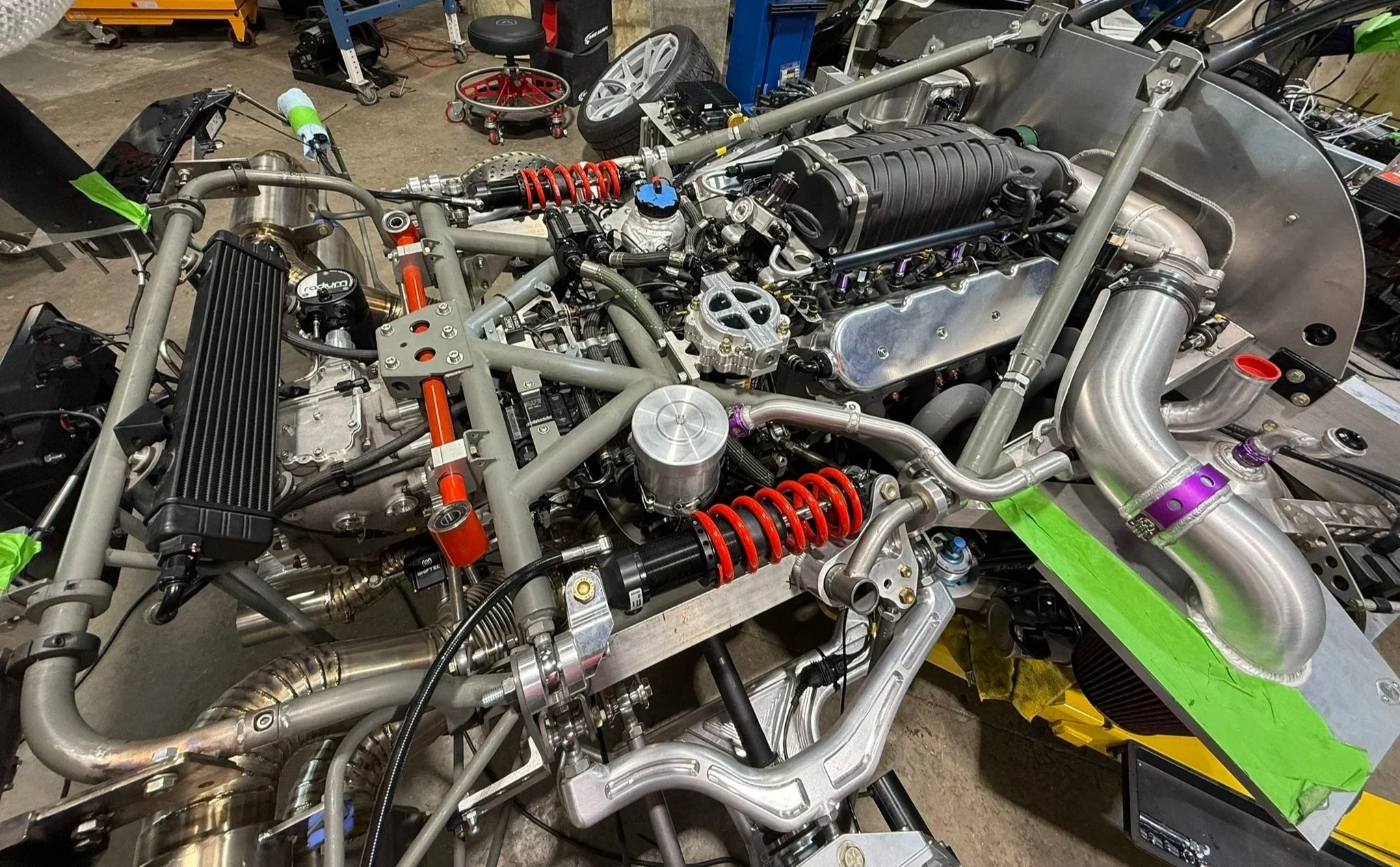
The chassis, engine and front harnesses arrived from Germany and there’s a lot to connect. According to the Bill of Materials (BoM) there are 115 connectors, 1,489 meters of wire and well over 1,000 pins.
These numbers don’t include the rear, nose clip, engine cover, climate, steering column or door harnesses. Keep in mind that some of the wire length is due to the fact that small gauge motorsport/aerospace Tefzel wires are used in lieu of larger gauge commodity wires because they match the capacity of the autosport connector pins, facilitate contra-helical twisting and improve harness flexibility. For example, a 20-amp circuit would be implement with four 22-gauge wires. So a motorsport harness will have more wires, but smaller diameter, lower weight and more flexibility that a functionally equalivent OEM harness.
Since all of the oil, fuel, cooling, etc. lines were already installed some thought was put into the best way to install the harness. The first step was to spread the 1:1 drawing on the bench, lay the harness on top to match and temporarily zip tie certain sections together to make it easier to feed those sections though tight spaces.
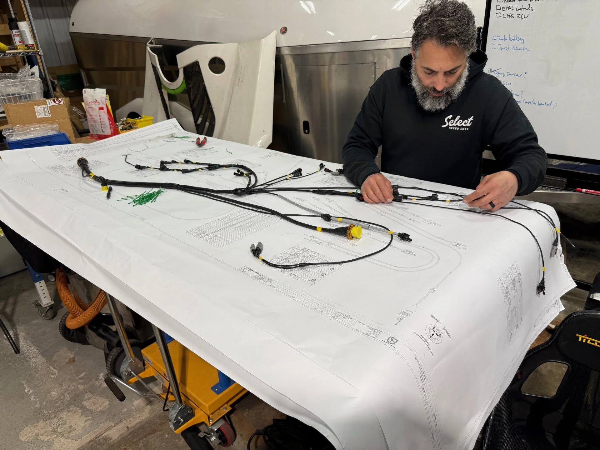
Laying out the engine harness on its 1:1 3’x 5’ plan
The bulkhead connectors were mounted to 0.60” laser-cut and CNC-bent stainless steel brackets. Depending on the shell size, they use M2, M2.5 or M3 x 6 mm long screws which are fiddly — easy to drop and hard to find. Fortunately, there are specifically designed nut plates so there is no need to deal with tiny nuts. They have distorted threads to prevent the screws from backing out and when bonded to the backside of the bulkhead flanges the screws are much easier to install.
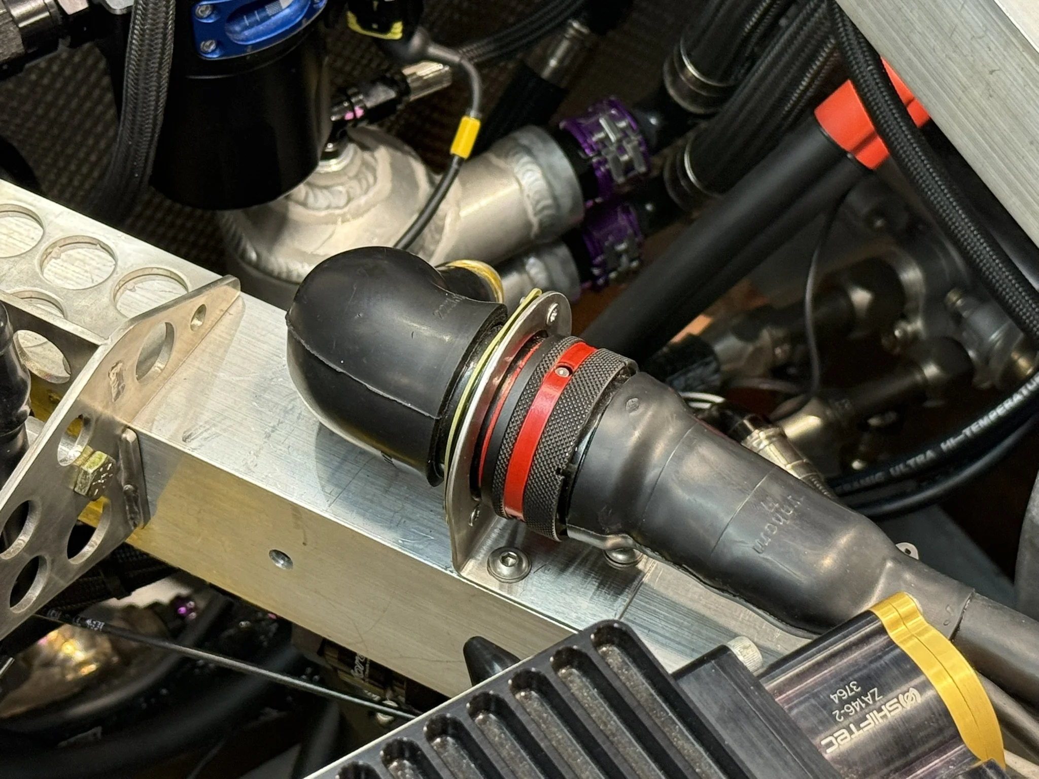
A single 128-pin connector connects the engine harness
Stefan did a great job measuring and designing the engine harness. The lengths were spot on and the wires pretty much disappear after the big connector.
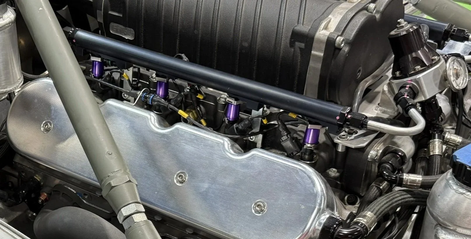
Several of the sensors are difficult or impossible to access without pulling the engine. To improve reliability, all engine sensors were potted, extended with Tefzel wire / Raychem DR-25 heat shrink and terminated with motorsport micro connectors. The micro connectors are compact as can be seen in the picture below.
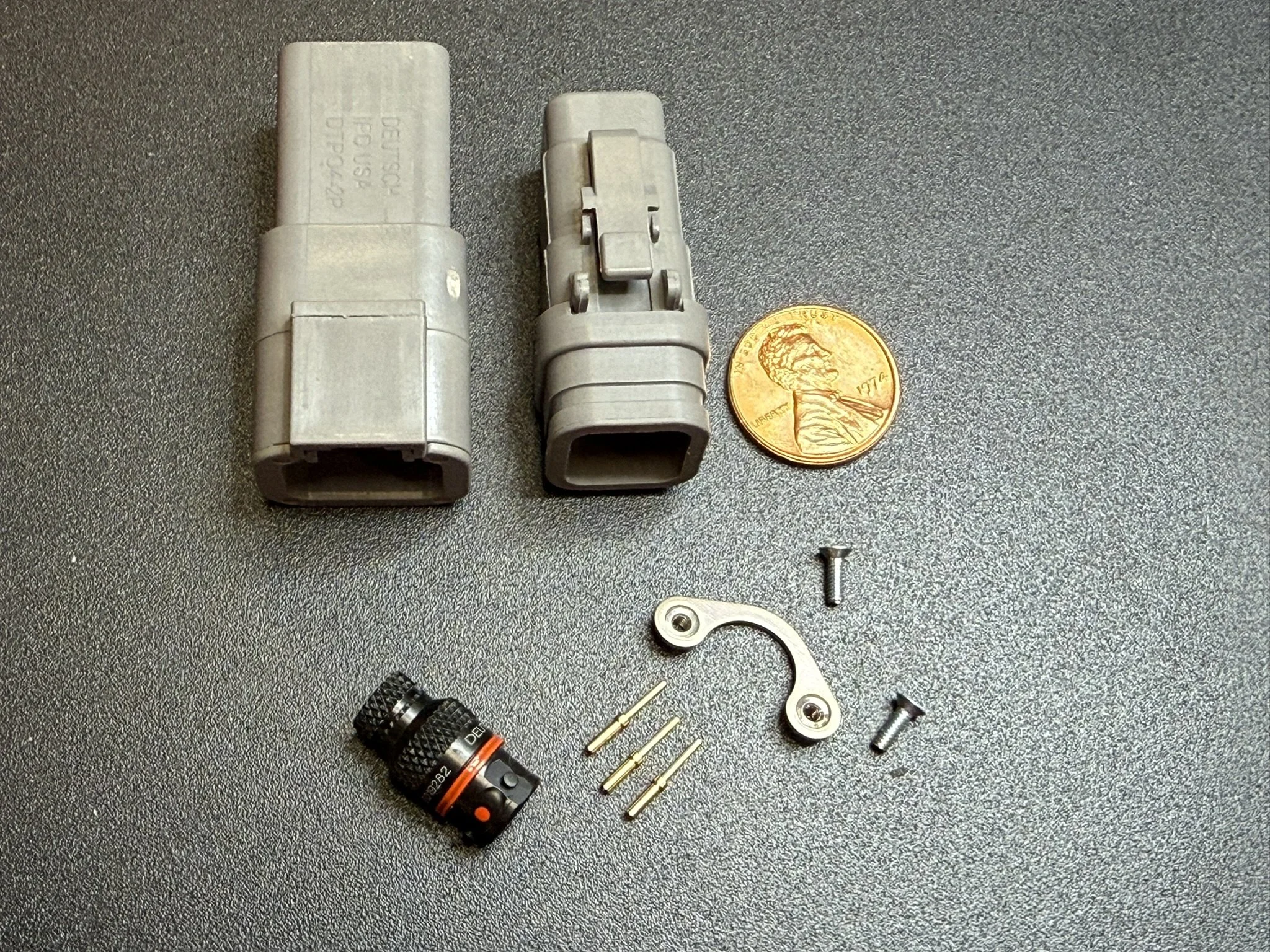
The autosport micro connector in the lower left corner is a #3 shell which can have up to six pins. The pins, nut plate (note that the connector isn’t a bulkhead) and M2 screws are for a #3 shell. F1 teams use even smaller #1 shells for low-current applications. For size comparison, the top left connector is a 2-pin DT series and the connector between it and the penny is a 6-pin DTM series.
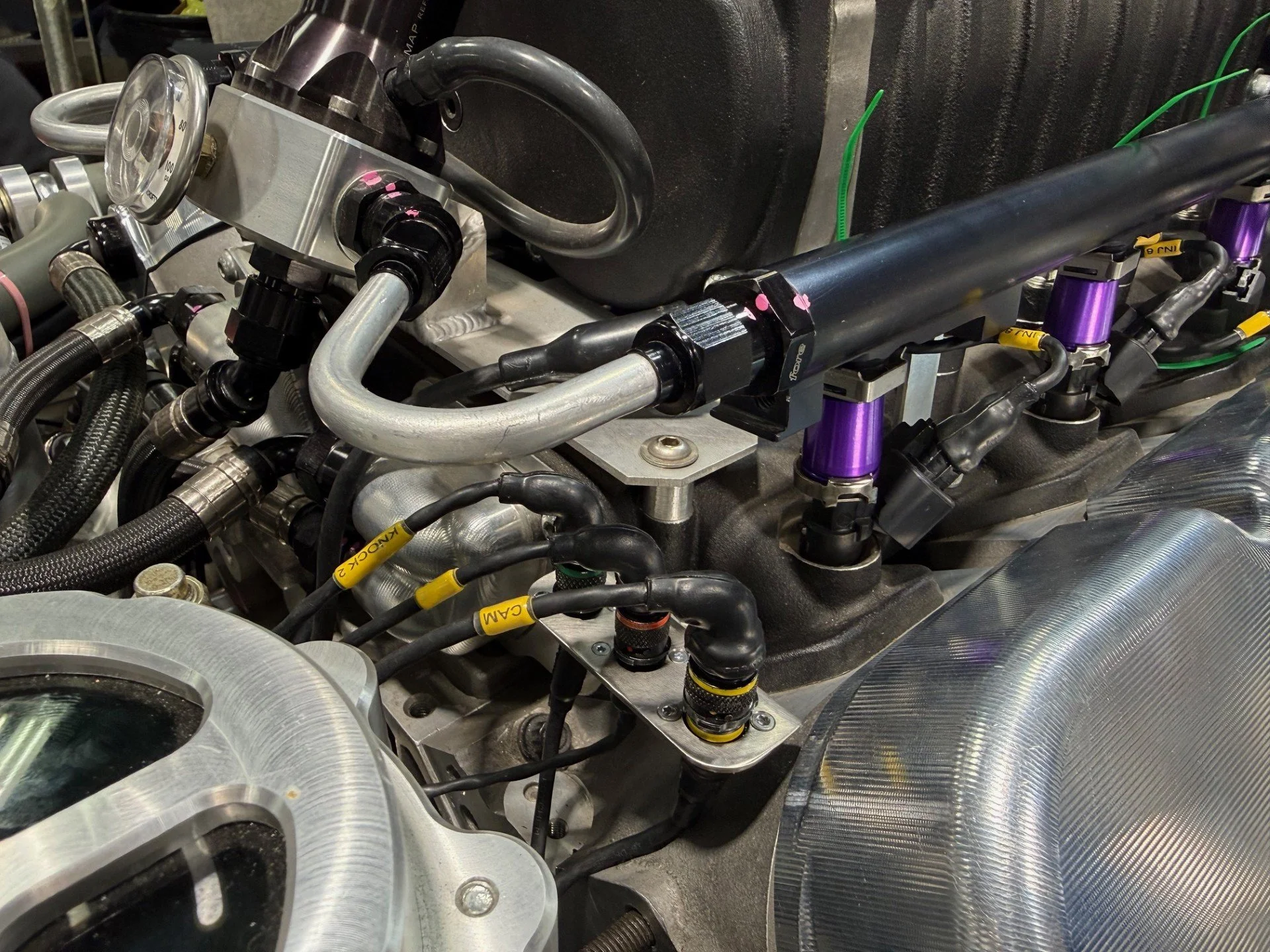
All of the engine sensor connectors were mounted to stainless steel plates. I 3D printed breakout boxes in other locations. but simple plates worked best when mounted to the engine.
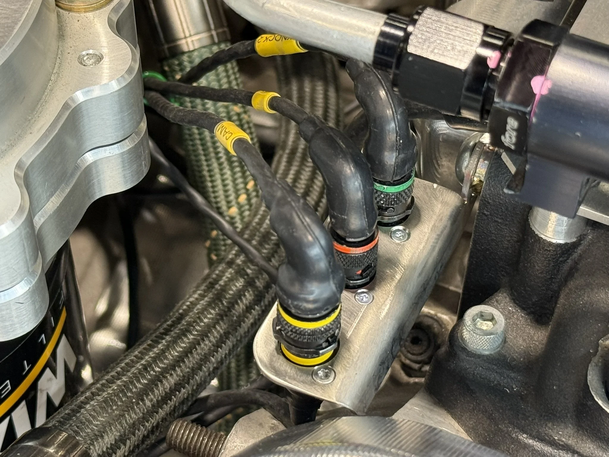
The cam (yellow), engine oil temperature (orange) and right knock (green) sensors
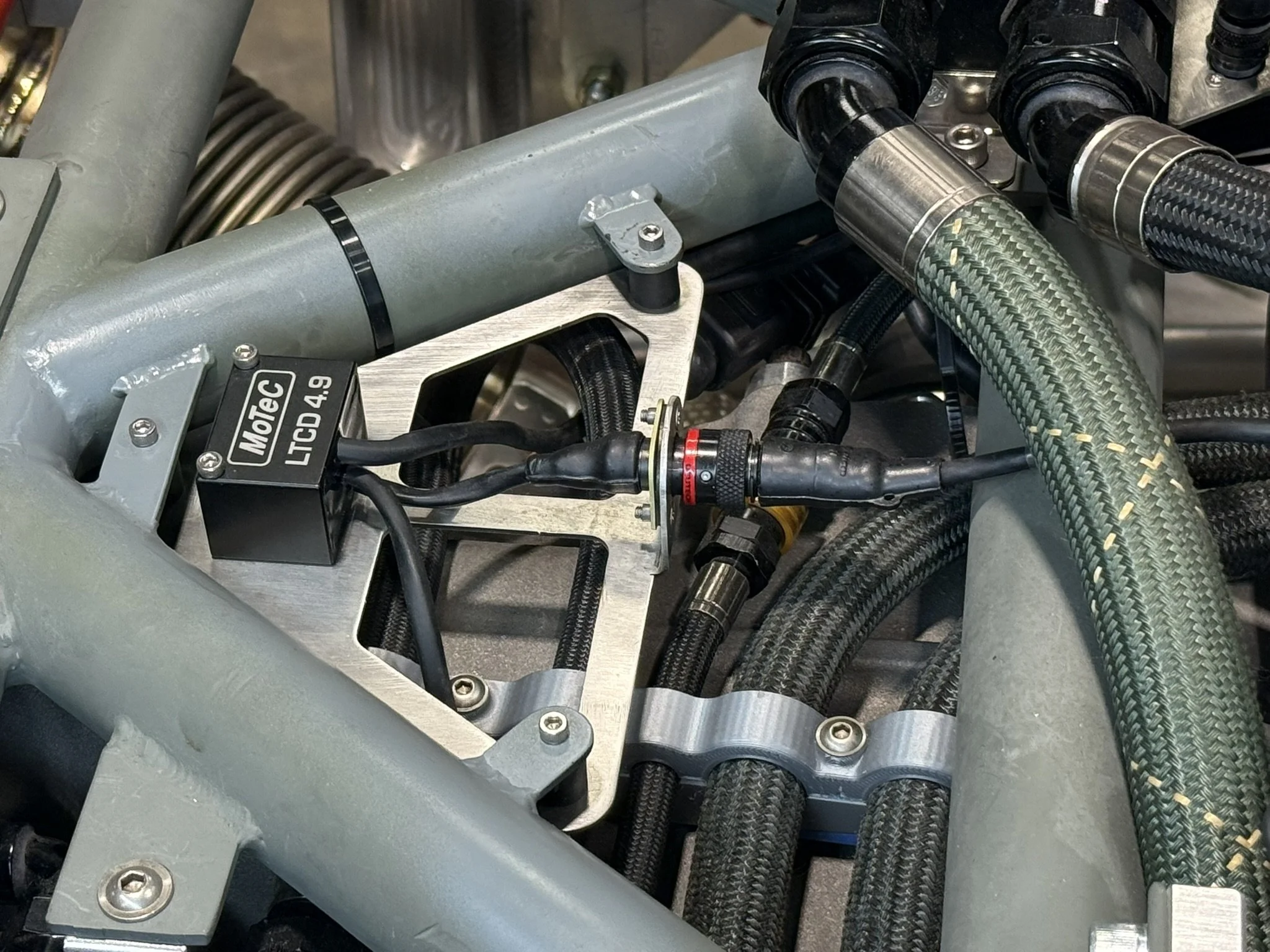
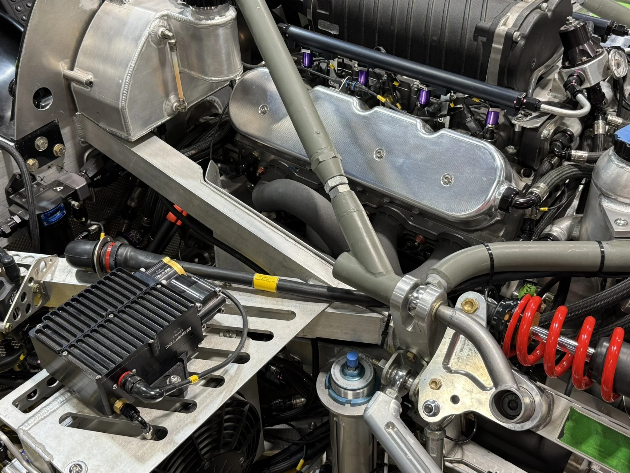
The dual lambda-to-CAN device was modified with a bulkhead autosport connector and mounted to a vibration isolation bracket
Crank sensor mounted to the valve cover