There’s nothing wrong with the grumble of an American V8. I have a cobra with a 427 side-oiler, Webber carbs and side pipes. It sounds bad ass and I love it, but I want to do something a little different for the SL-C. I considered doing a 180-degree crossover exhaust, but there is no room to do it unless I cut through the top of the body which I don’t want to do. So, I was planning on a simple exhaust using the OEM exhaust manifolds because, according to my engine builder, custom headers may look cool, but they won’t generate any more power and will only lead to heat, fitment and leaking issues.
However, I keep looking at the 2-3/8” between the Daily dry sump and the bottom of the car. I considered lowering the engine to lower the center of gravity, but the supercharger snout and induction tube would hit the 2” x 6” chassis tube. If this were a pure race car, I’d notch the chassis and lower the engine, but for my use case that doesn’t make sense. It occurred to me that the space under the oil pan could be used for a 180-degree crossover exhaust.
So, what’s a 180-degree crossover exhaust? To understand that you need to first understand the high-level differences between a cross-plane and flat-plane engine. A cross-plane crank has journals separated by 90 degrees and a flat-plane crank has journals separated by 180 degrees. When viewed along the axis of rotation a cross-plane crank looks like a cross (i.e., “+”) and a flat-plane crank appears flat (see image below). If you think about it, if two lines are 180-degrees apart they are parallel and will appear flat when the plane that intersects them is viewed on its edge.
The following table summarizes the high-level pros and cons of each approach.
With the exception of the recent Mustang Shelby GT350, all American V8s have a cross-plane crank and many “exotic” cars (e.g., F1, Ferrari, Lamborghini, McLaren, etc.) have flat-plane cranks. There has recently been a lot of hype that cross-plane engines are exotic. This is a pile of bull you know what.
Firstly, a cross-plane crank can only be used on an engine with a number of cylinders divisible by eight, which for cars means 8 or 16 cylinders. Secondly, flat-plane cranks are used in everything from Honda Civics to mail trucks. This article does a great job discussing the nuances between cross and flat-plane engines and the origin of the recent hype.
OK, back to the exhaust… Flat-plane cranks optimize the intake and exhaust processes by alternating pulses between the the left and right sides of the engine — L-R-L-R-L-R… These even pulses, when combined with a high-revving valve train, are what gives Ferrari’s and Lamborghini’s their “exotic” sound.
A cross-plane crank doesn’t alternate pulses between the left and right sides. It has a R-R and L-L in the middle of the firing sequence which is what creates the “American” rumble. This also creates a crowded condition in the collector because two exhaust pulses, separated by only 90 crank degrees, are flowing through the collector. This requires a larger collector and reduces scavenging, both of which have a negative effect on power.
Enter the 180-degree crossover exhaust. Rather than plumbing all the tubes from each side into the same 4-1 collector, two of the tubes from each side are crossed to the other collector to create evenly spaced exhaust pulses — just like a flat-plane engine. This produces a broad power band (i.e., smaller collector), increases scavenging and results in a sound with less rumble, at least at mid to high RPMs.
The original GT40s, including the ones that won Le Mans in the 60’s, had 180-degree crossover exhausts. The picture below is of an original GT40. You can see why the exhaust is commonly referred to as a “bundle of snakes.” Most headers are made by sectioning fixed-radius, mandrel-bent U’s and welding them together. If you look at the graceful curves on the headers below, it’s clear that they weren’t made that way. I’m not sure how they did it, but it took some serious skills.

Yeah, I realize that a crossover exhaust will be a lot of work, create potential leaks and create heat issues, but if it were easy everyone would do it. While the original bundle of snakes increased power my fitment constraints may cost me some power (e.g., longer and skinnier primaries, increased number of bends, etc.), but I have excessive power so that’s not a concern. So why am I going to try and do it? For the sound. The sound of the Vette in the following video is bliss… please ignore the irresponsible driving.

That car has an LS7 with equal-length 36” long primaries. For fitment reasons the primaries are 1-3/4” and the collectors are flat. Round collectors, particularly when the primaries are sequenced to fire in a circular pattern (clockwise or counterclockwise), offer superior performance due to improved scavenging.
I conceptually understood that two of the primaries from each side had to be crossed over, but how a double pulse on each side occurred and how the tubes were routed wasn’t intuitive to me. To get my brain wrapped around things I put together the following diagram which illustrates the exhaust pulses down the left and right cylinder banks for eleven compression strokes:
Note that the stock exhaust creates a double pulse in each cylinder bank; the right during compression strokes 4 and 5 and the left during compression strokes 8 and 9. The 180-degree crossover exhaust crosses these primaries to the opposite side which creates a symmetrical pulse down the left and right cylinder banks.
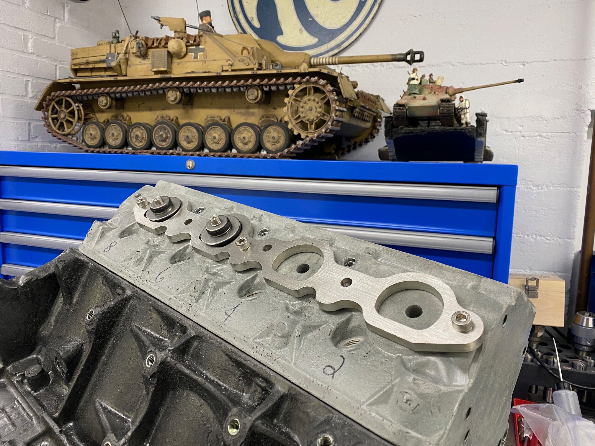
What do you buy for an 8-year old when a pandemic is looming? LEGOs of course. What do you buy a 50ish-year-old boy? Big-boy LEGOs. Specifically, a plastic LS7 engine block and an 1-7/8” icengineworks set to mock headers.
The plastic blocks are attached to the exhaust flange using a block starter / tube adapter which are composed of pieces of rubber sandwiched between stainless steel disks. When the screw is tightened the rubber is compressed causing it to bulge. The large piece of rubber grips the inside of the exhaust tube and the small piece of rubber grips the plastic block.
I didn’t have short starter tubes tacked to the exhaust flange as suggested by the instructions so I tried to insert the block starters directly into the exhaust manifold. That didn’t work because the exhaust ports are D shaped and the starter blocks are round. A little grinding was all that was required to get everything to fit. From left to right; front of starter block, rear of starter block, and disassembled starter block with modified front and rubber disks.

I had to drill a relief hole in the middle of exhaust port to accommodate the nutsert and screw on the backside of the tube starter. I subsequently realized that I had the flanges mounted upside down ;-)
I’m not sure if I’ll be able get it to work out the way that I want, but it gives me something to do during the pandemic!