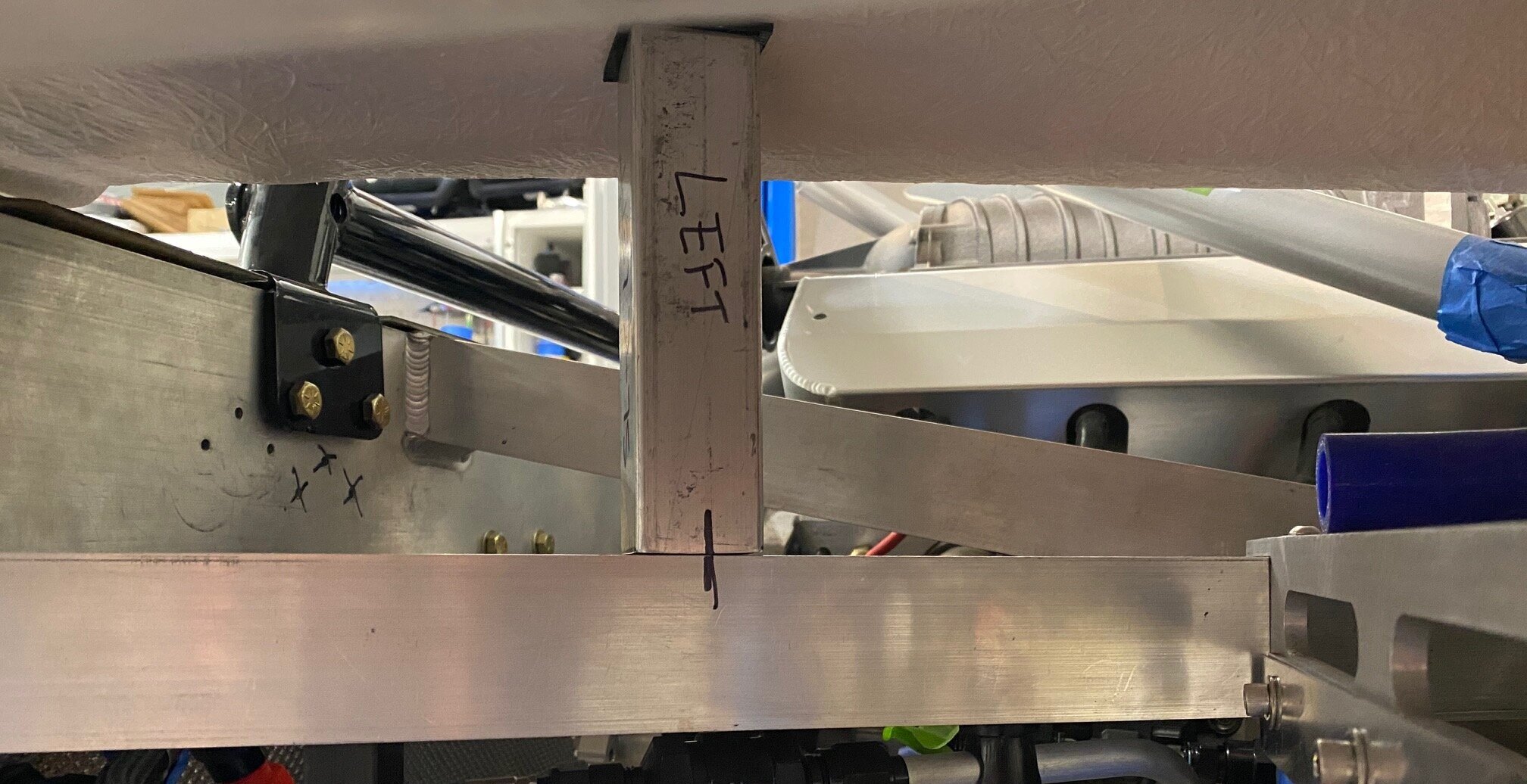
The space between the body and the chassis is tight and the prior induction tube put a small crack in the fiberglass. It’s difficult to figure out how much space you have with the body in place. However, when the body is removed the tail section sits too low. To solve this, I cut two temporary tubes to support the tail at the correct height which makes it easy to check clearance when the body is off. The vertical sharpie line spanning the temporary support and the chassis makes it easy to align the support and the rubber on top protects the fiberglass.
I was concerned that I’d need to scallop the 2” x 2” chassis tube or use an oval induction tube, but a 45-degree bend was all that it took… well, that’s only the case because we previously positioned the throttle body in the right place and used a tight-90-degree elbow on the cold air box lid.

I used a -64 AN (i.e., 4”) AdelWiggens tube connector to connect the elbow to the induction tube. These clamshell-style connectors have been used in aerospace for over 30 years. They can be opened and closed with a single hand and require no tools. They have some impressive specs, all overkill for an induction tube, but that’s how I roll LOL
Operating Pressure: 125 psig
Proof Pressure: 250 psig
Burst Pressure: 375 psig
Axial Displacement: 0.250"
Angular Misalignment: +/- 3.5 Degrees
I had to look up what psig was. It’s pounds per square inch gauge which is the pressure relative to atmospheric pressure as opposed to pounds per square inch absolute (psia) which is pressure relative to a vacuum. I guess if you manufacture parts that can be used terrestrially or in space you need to spec things that take atmospheric pressure or the absence of it into account.
The ferrules are typically butt welded, but I counterbored their IDs on a lathe to allow the them to fit over the tube. This ensured that they were perfectly concentric to the induction tube. Things were a bit sticky out-of the-box so I cleaned the grease off of the o-rings, ferrule grooves and sleeve and applied a thin layer of lithium grease.
Apparently the standard aerospace color for these types of clamps is purple, similar to the red/blue standard for AN fittings. I want to be 100% clear here. It’s purple and not any shade of pink!
The induction system is done other than the cold air box and the duct, neither of which are needed to start the engine.
