Other than the exhaust tips and ceramic coating, the exhaust system is done. I now need to fabricate eight heat shields to solve all of the self-inflicted heat management challenges. The first heat shield protects the transaxle from the X-Pipe and exhaust cut outs.
The heat shield was fabricated from 0.048” stainless steel. I chose it over aluminum because it would warp less during welding, it has significantly lower thermal conductivity and it allowed a thinner material to be used.

It was fairly involved to get right:
11 laser-cut pieces
20 CNC bends
7 heat/vibration isolators (purple parts)
A fair amount of welding (green pieces to the gray piece
These parts required me to learn a few new sheet metal tricks. The recessed box required five corner bend reliefs. Fortunately, SolidWorks has a specific feature which makes that easy. The two sloped sides required me to modify their flanges. Specifically, the CNC brake operator pushes the edge of the part into a back gauge to ensure that the depth and angle of the bend is correct. This requires that edge to be parallel to the bend line — which it wasn’t.
As can be seen in the picture below, the solution was to extend the sloped sides to create an edge parallel to the bend line. The extension is attached via small tabs to facilitate removal. After the part arrived, I cut the extension off and sanded the edge smooth. The tabs required more effort than I anticipated to remove. I took a closer look at SCS’s guidelines and it recommends that the tab width is 50% the material thickness which seems right (mine were twice that wide). They also recommend that each tab is spaced out by 1x the material thickness which seems a seems a bit excessive. I had the corners precut so I only needed to sand the straight edge with the tabs.
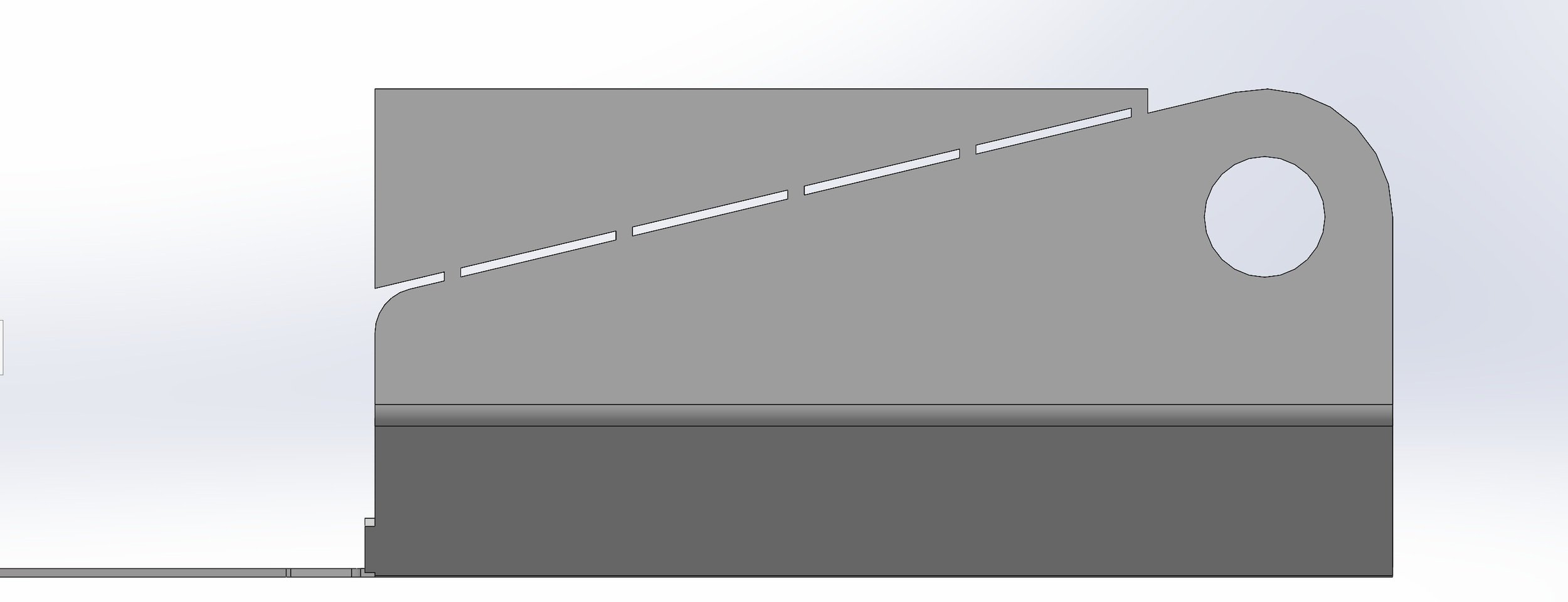
The sloped side has been extended to create an edge that’s parallel to the bend line. The tabs facilitate the removal of the extension.

Welding has been completed. Small stitch welds were used to reduce warping.

I 3D printed sections of bend profiles to check fitment and SCS’s bends were spot on. Note that the holes in the stainless have 0.74” doughnuts welded to the outside to provide the correct thickness for the isolators.

The dropped box on the right side accommodates the pneumatic shift servo

Front view
The fit was excellent. Once I finish the remaining seven shields, I’ll have them ceramic coated with Cerakote and I’ll apply one of the ZircoFlex or ZiroForm products to the underside.